
GC
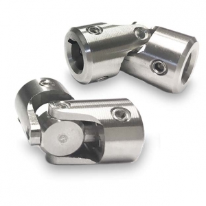
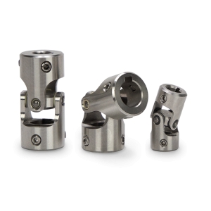
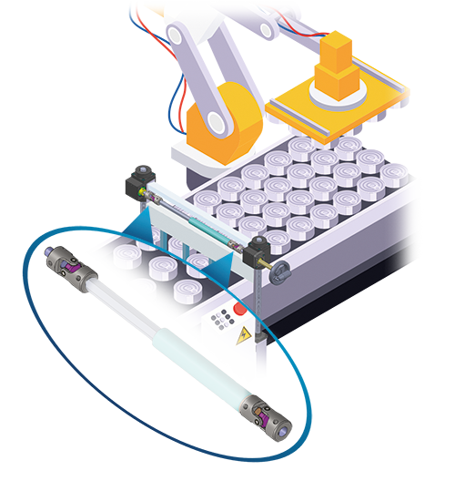
Standard universal joints
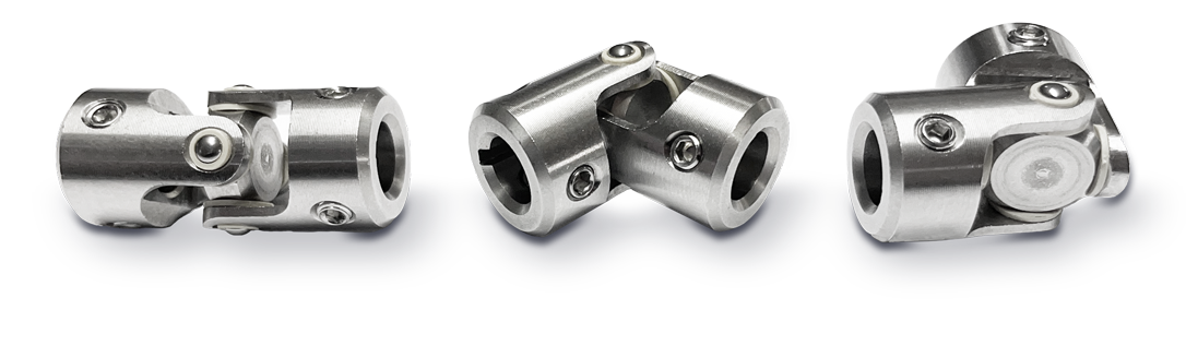
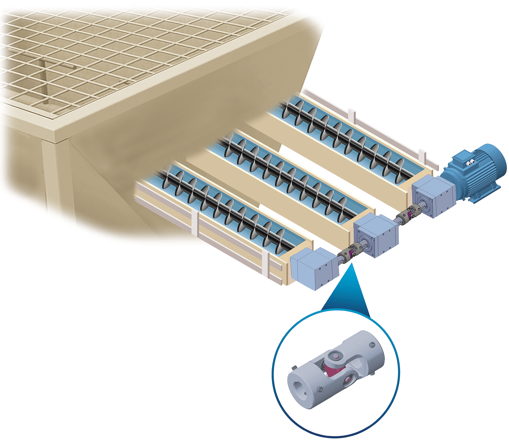
The GC universal joints are used for the transmission of torque between of
non-aligned elements.
• Maximum working angle 45°.
• Suitable for intermittent (UI) and continuous operation (UC).
• Entirely machined from solid AISI303 stainless steel.
• Sliding bushes in self-lubricating plastic material.
• Maintenance free.
• Available bores: ø6 - ø8 (combinable with each other);
ø10 - ø14 (combinable with each other).
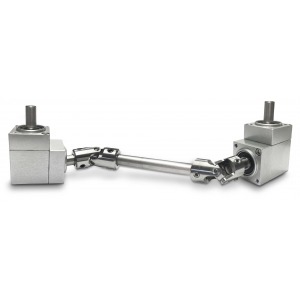
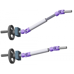
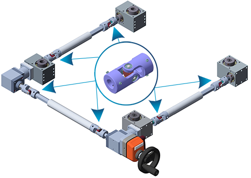
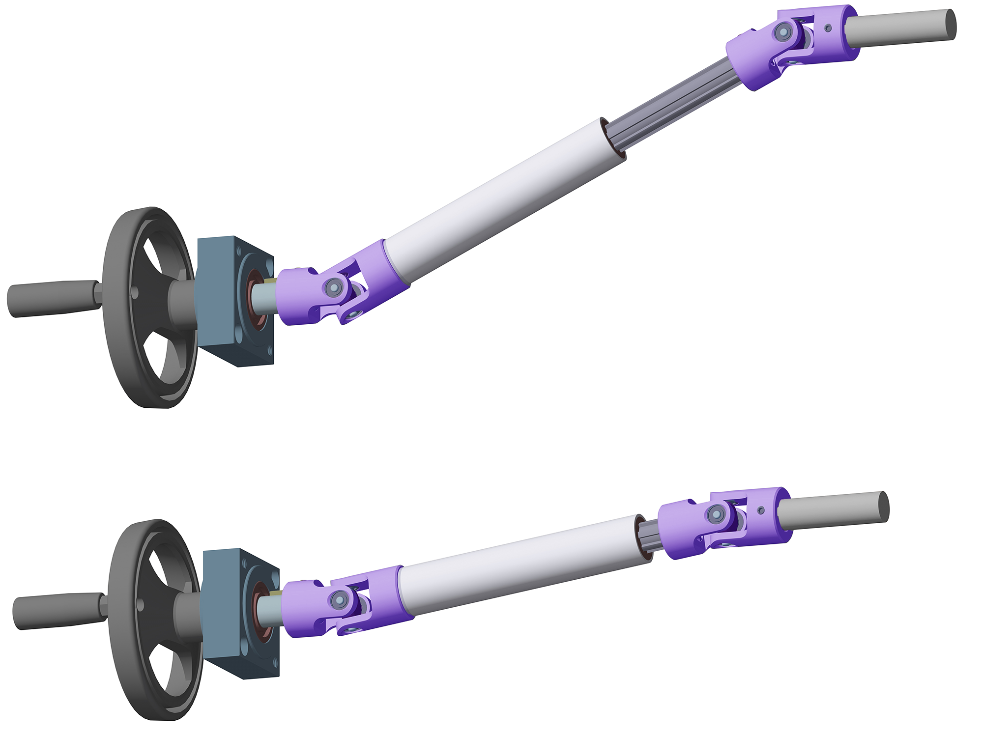
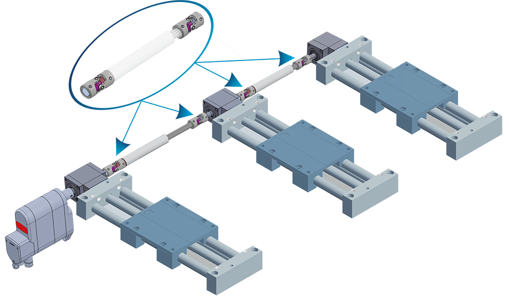
• Flexibility of application with rigid and telescopic shafts, angular gearboxes,
gear-reducers and screw jacks.
• Main features: universal application, high reliability, extreme precision and
ease-of-use.
Photogallery
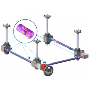
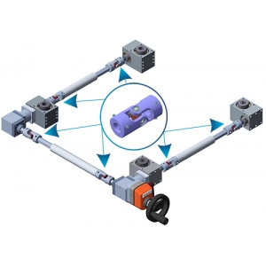
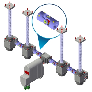


| APPLICATION EXAMPLES | |
 |
 |
 |
 |
 |
 |
 |
 |
 |
 |
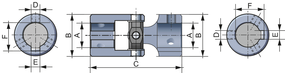
| DIMENSION TABLE «GC» | ||||||
|
|
||||||
| VERSIONS | A | B | C | D | E | F |
| GC06 | Ø06 | Ø16 | 35 | M4 | 2 | 7 |
| GC08 | Ø08 | Ø16 | 35 | M4 | 2 | 9 |
| GC10 | Ø10 | Ø24 | 52 | M5 | 3 | 11,4 |
| GC14 | Ø14 | Ø24 | 52 | M5 | 5 | 16,2 |
|
Bores: ø6 - ø8 (combinable with each other); ø10 - ø14 (combinable with each other). |
||||||


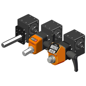
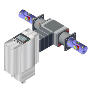
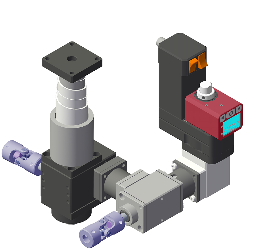
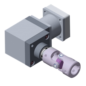
Compact reducer with high-performance, complete with fixing flange and extension shaft for display with ‹OP3› position indicator.
➜ for more complete information, see RD40-FL-OP3/EP3
Compact reducer with high-performance, complete with fixing flange and extension shaft for display with ‹OP3/EP3/OP7/EP7› position indicators.
➜ for more complete information, see RD50 FL-OP3/EP3/OP7/EP7
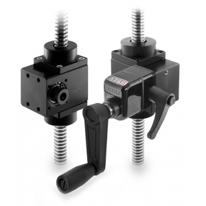
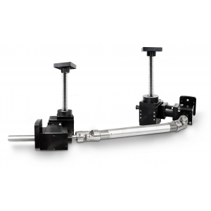
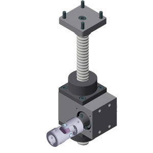
MAR40: The FIAMA series of screw jacks is a modular mechanical system, for a complete and versatile solution, which transforms rotary movements into linear «push/pull» movements.
➜ for more complete information, see sec. "Right-angle drives..." in the drop-down menu on the left.
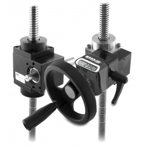
MAR50: The FIAMA series of screw jacks is a modular mechanical system, for a complete and versatile solution, which transforms rotary movements into linear «push/pull» movements.
➜ for more complete information, see sec. "Right-angle drives..." in the drop-down menu on the left.
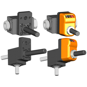
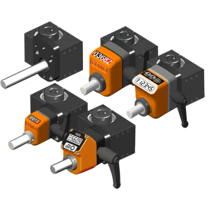
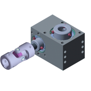
Angular gearbox 66/22 with flange MØ8x55 FL-OP2, designed for connection with the position indicator. It ensures precise adjustments and accurate monitoring of the position, enhancing stability and reading accuracy. The flange, made of black anodized aluminum, perfectly matches the gearbox case, both featuring the same elegant and durable finish.
➜ for more complete information, see 66/22
Angular gearbox 66/4 with flange MØ14x68 FL-OP3/EP3, designed for connection with the position indicator. It ensures precise adjustments and accurate monitoring of the position, enhancing stability and reading accuracy. The flange, made of black anodized aluminum, perfectly matches the gearbox case, both featuring the same elegant and durable finish.
➜ for more complete information, see 66/4

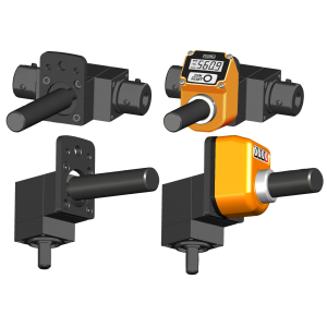
Angular gearbox 66/5 with flange MØ14x68 FL-OP3/EP3 and MØ14x80 FL-OP7/EP7, designed for connection with the position indicator. It ensures precise adjustments and accurate monitoring of the position, enhancing stability and reading accuracy. The flange, made of black anodized aluminum, perfectly matches the gearbox case, both featuring the same elegant and durable finish.
➜ for more complete information, see 66/5
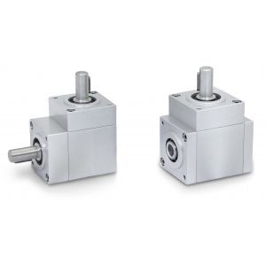
66/6: these gearboxes are suitable for the transmission of rotating motions between two shafts at right-angles.
• Available with reduction ratio: 1:1
• Aluminium case, black anodised; stainless steel shafts AISI 303
• Torque 45 Nm
➜ for more complete information, see sec. "Right-angle drives..." in the drop-down menu on the left.
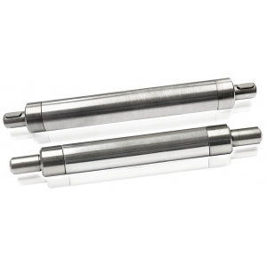
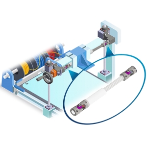
AR: rigid shafts used to directly connect parts which are perfectly aligned without any offset.
• Suitable for manual and motorized motion transfer
➜ for more complete information, see the drop-down menu on the left.

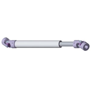
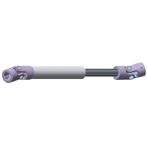
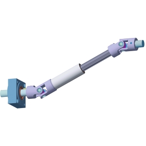
ATE: telescopic shafts are ideal to connect two elements with a constant or variable center to center distance.
• Torque from 5 Nm to 10 Nm.
• Manufactured entirely in AISI 304 stainless steel. Sliding bushings made of self-lubricating plastic material.
➜ for more complete information, see sec. "Flexible & semi-rigid shafts..." in the drop-down menu on the left.
Photogallery
Richiedi l'accesso
|
EFFICIENCY TABLE |
||
|
|
||
| 90% | 85% |
65% |
|
|
 |
|


| SPEED/TORQUE | |||
| GC06-GC08 | GC10-GC14 | ||
| RPM | Nm | RPM | Nm |
| 100 | 7 | 100 | 14 |
| 200 | 6 | 200 | 12 |
| 400 | 5 | 400 | 10 |
| 600 | 3,5 | 600 | 7,5 |
| 800 | 2,5 | 800 | 6 |
| 1000 | 1,5 | 1000 | 4 |
|
The values shown are in Nm % with a working angle equal to 10 °. In case of intermittent use (UI) it is possible to have increased torque values 30% for short operations. |
|||
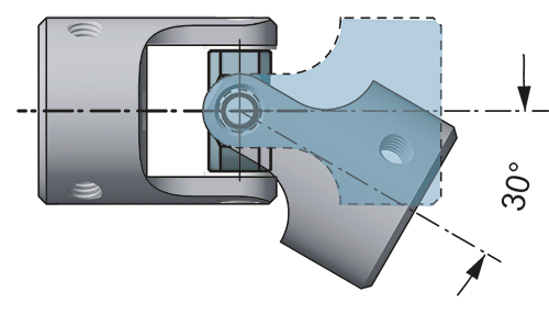
| WORKING ANGLE | |
| ANGLE (°) | COEFFICIENT (c) |
| 0 | 1.25 |
| 5° | 1.25 |
| 10° | 1 |
| 20° | 0.8 |
| 30° | 0.45 |
| 40° | 0.3 |
| 50° | 0.25 |
|
For an diverse working angle than 10°, the torque must be modified according to the coefficient (c) compared to the angle variation. |
|


