




Gearboxes - General information

|
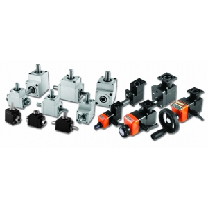
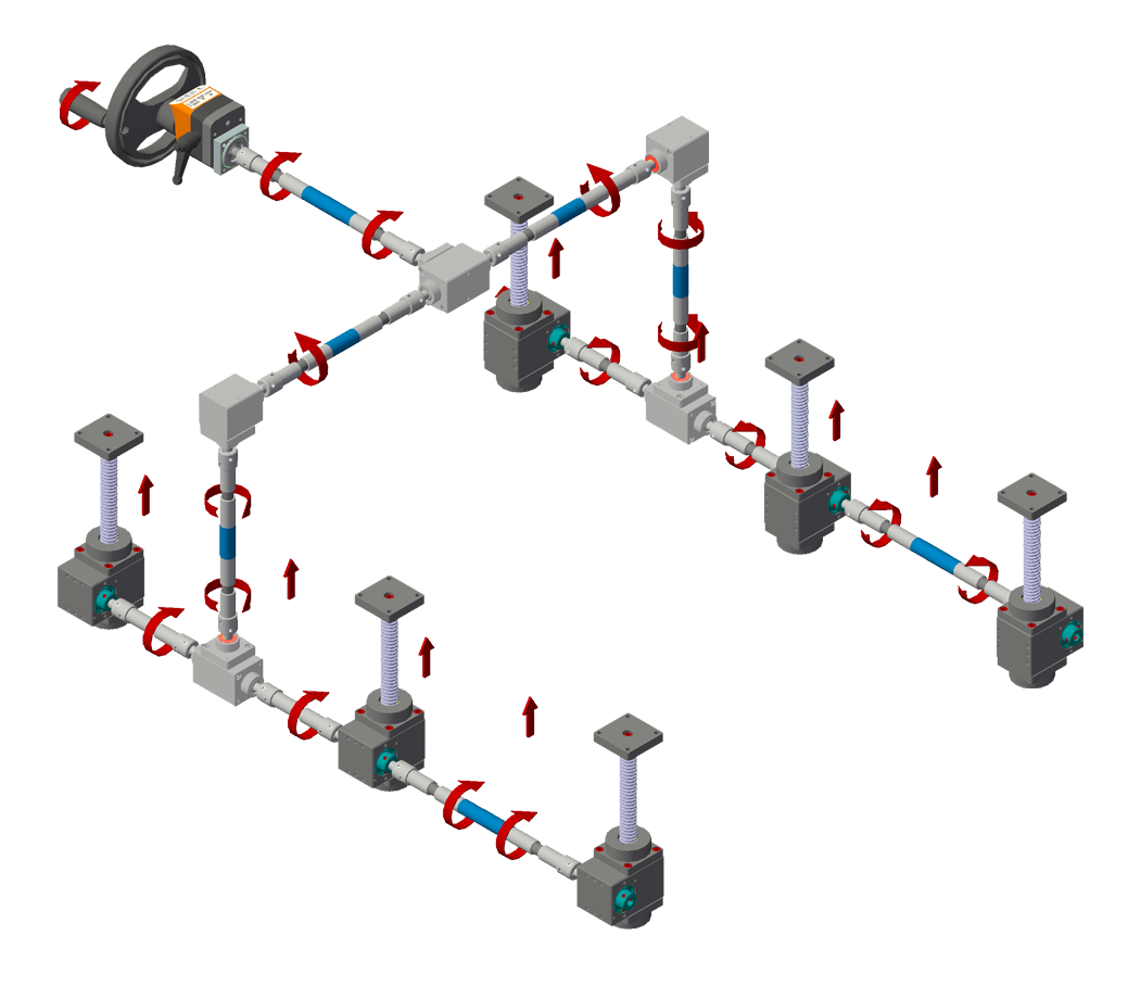
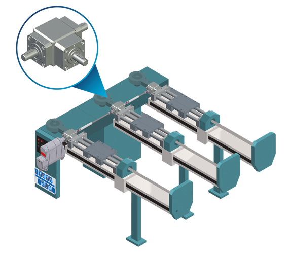
● Universally applied, suitable for all industrial applications where it is necessary to transmit rotary motions between two shafts at right angles. |
|
● Compact and modular design, highly adaptable, easy installation. |
|
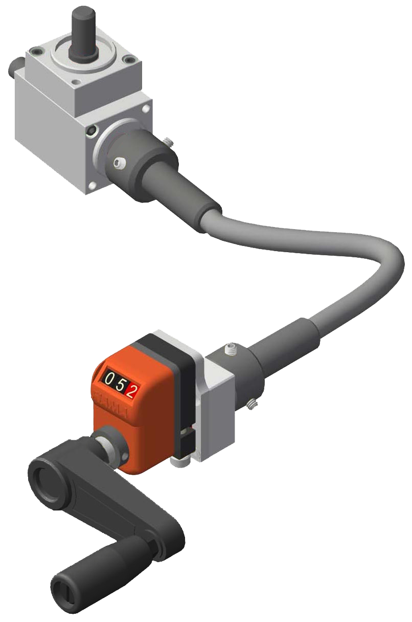
● Manual or motorized motion, flanges available for coupling to machines, motors, display units. |
|
● Wide range of input and output shafts with keyways. |
|
● Special versions available upon request. |
|
Gearboxes models ‹66› for intermittent use |
|
● 5 sizes identified as 66/22 - 66/4 - 66/5 - 66/6 - 66/8. |
|
● 5 configurations identified as «A»- «B» - «C» - «D» - «E», with protruding output shafts identified as M, blind and through females as F. |
|
● Standard shaft diameters from Ø 6 to Ø 20 mm. |
|
● Models with straight bevel gears, suitable for moderate loads and speeds |
|
● Models with spiral bevel gears for higher precision, silent operation, and higher output torque. |
|
● Flanges for mounting on the machine side and for motors. |
|
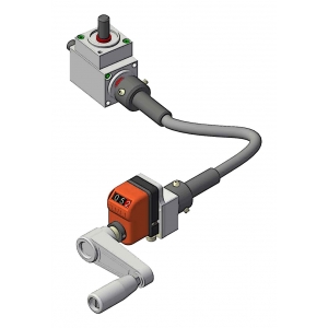
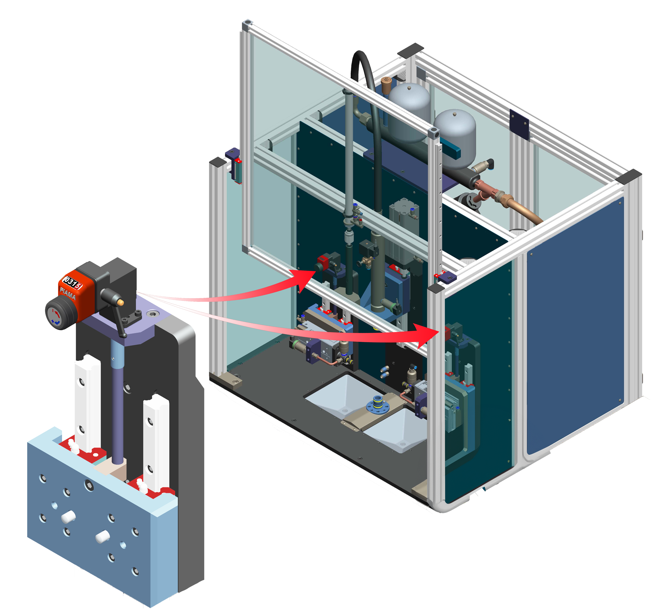
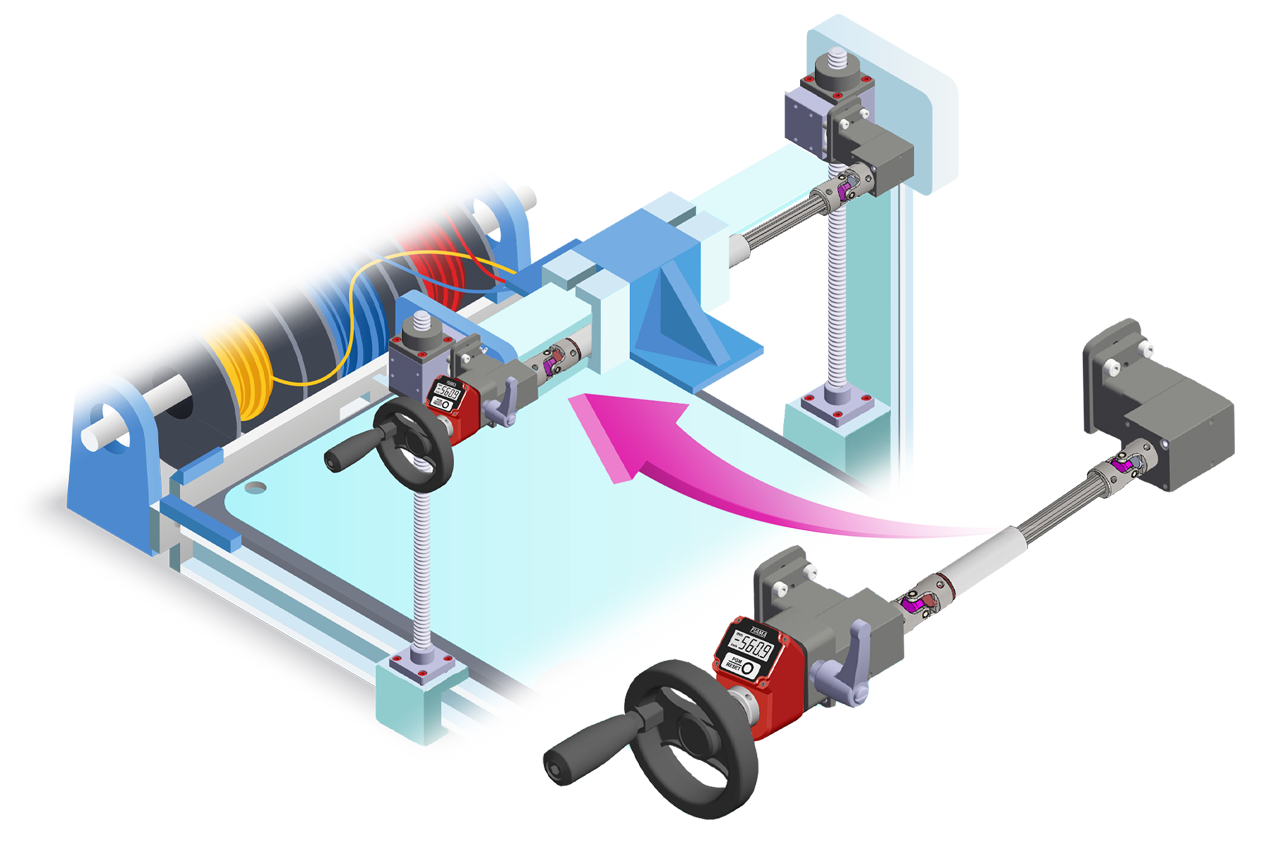
● Mounting flanges and shaft extensions for adjustments displayed with mechanical and electronic position indicators. |
|
Gearboxes models ‹66_UC› for continuous use |
|
● 3 sizes identified as 66/4UC - 66/5UC - 66/6UC. |
|
● 4 configurations identified as «A» - «B» - «C» - «D», with protruding output shafts identified as M, blind and through females as F. |
|
● Standard shaft diametersfrom Ø 8 to Ø 20 mm. |
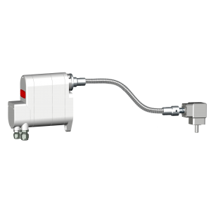
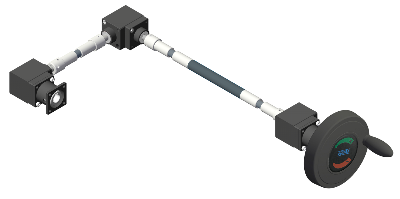
Photogallery



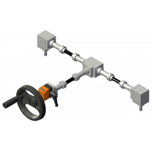
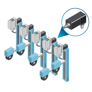
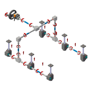

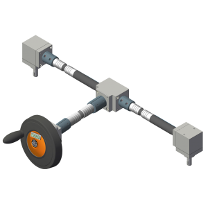









|
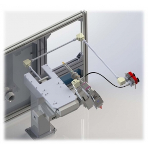
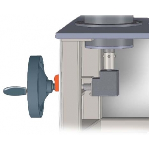
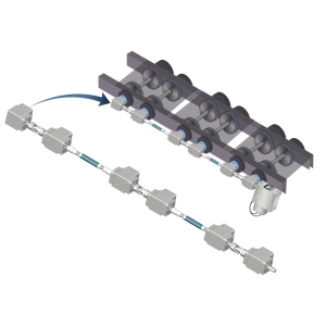
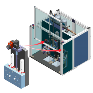
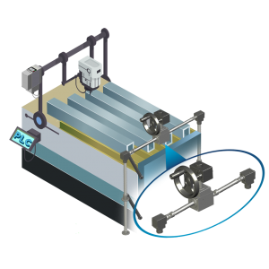
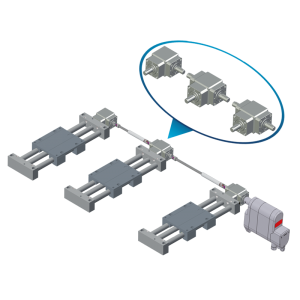
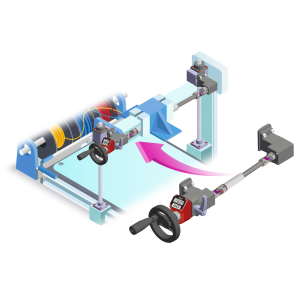
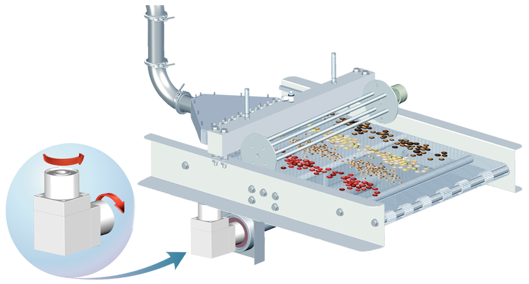
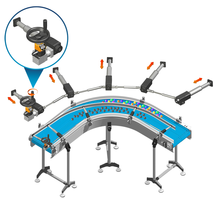
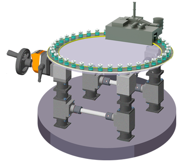
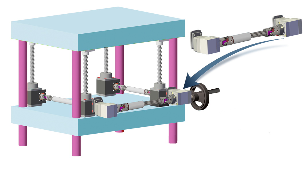
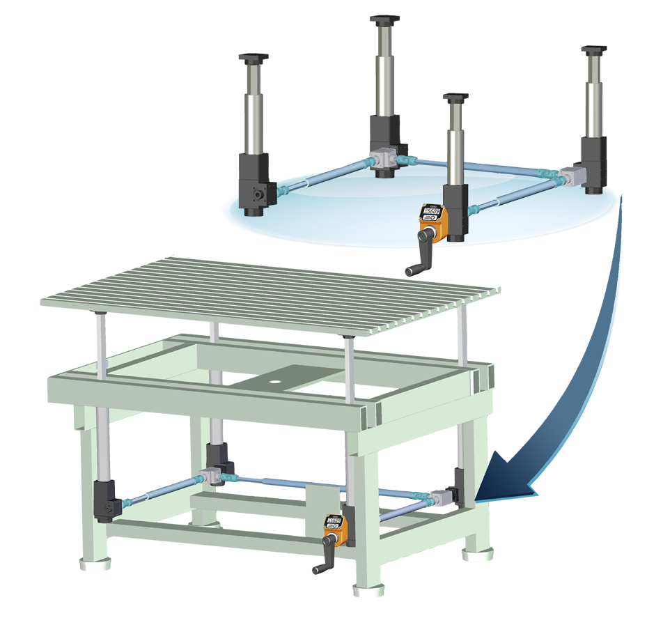
APPLICATION EXAMPLES |










| GENERAL DATA | |
| Casing material: | |
| grey anodized aluminum for 66/4 - /5 - /6 - /8; black anodized aluminum for 66/22,RINV-OP; AISI 303stainless steel (on request) | |
| Shaft material: | |
| AISI 303 stainless steel | |
| Gear material: | |
| steel with wear-resistant surface hardening treatment | |
| Gear play tolerances: | |
| from 0.1 ° to 0.75 ° (smaller tollerances on request ①); minimum backlash and axial play |
|
| Bearings: | |
| ball-bearing of the best brands suitably sized to ensure long life | |
| Lubrication ②: | |
| long life grease; on request available H1 grease for food/pharmaceutical industry, and for high temperatures | |
| Transmission ratios ③: | |
|
1:1 - 1:2 reduction, 2:1 multiplication; the total efficiency of the transmission is 90% |
|
| Working temperature: | |
|
-10° + 50° |
|
|
Available torques: |
|
|
from 2 Nm to 80 Nm |
|
|
① Excessive play reduction, could cause blockage of the transmission; the play tends to grow with the gear wear |
| LIFETIME CALCULATION | |
| Theoretic Expected Life ▪ = 10.000h x fu (factor of use) Suggested torque (Nm) fu = -------------------- Applied torque (Nm) ▪▪ |
|
|
▪ The lifetime of 10.000h considers the following conditions: |
|
NECESSARY DATA FOR THE SELECTION OF THE GEARBOX |
|
● Transmissible Torque (Nm) - the rotational force that can be transmitted without causing damage or reducing performance |
|
● Rotational Speed (rpm) - the number of complete rotations made per minute |
|
● Gear Ratio - the ratio between input and output speed. |
|
● Mounting Configuration - orientation, type (solid or hollow) and diameter of the shaft |
|
● Weight and Size - space and weight limitations that the angular gearbox must adhere to |
|
● Operation - intermittent or continuous use |
|
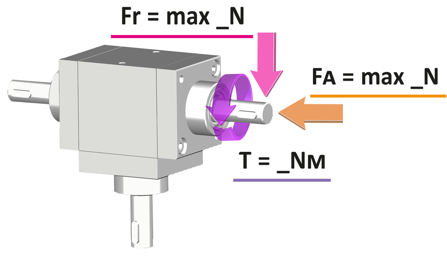
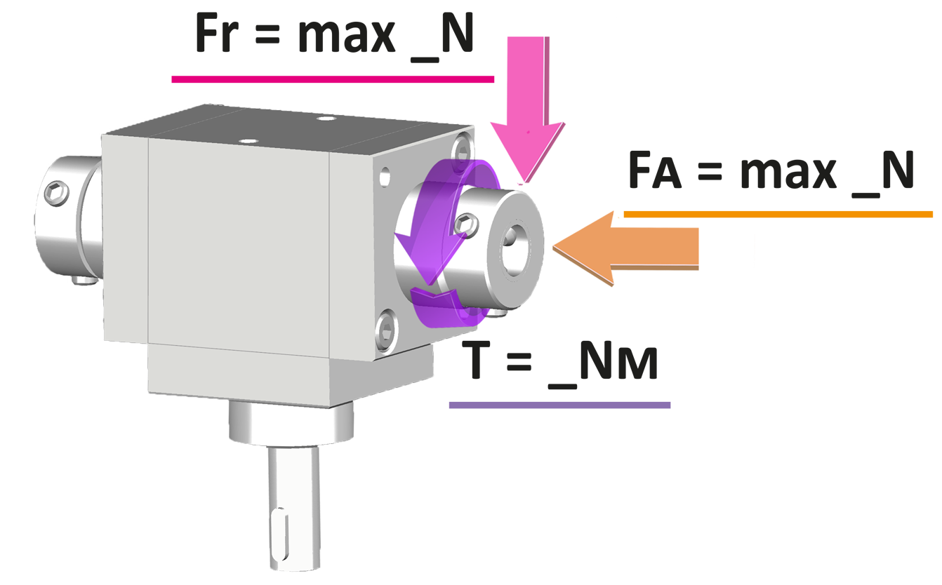
● Radial and Axial Loads - forces that act perpendicular (radial) or along the axis of rotation (axial) |
|
● Backlash and Precision - mechanical precision requirements and the permissible backlash in the system |
|
● Nominal Power - the power that the angular gearbox must be able to handle, expressed in kW |
|
● Working conditions - environmental conditions such as temperature, humidity, presence of dust or chemicals |
|
GLOSSARY |
||||||||||||||||||||||||||||||||||||||||||||||||||||||||||||||||||
|
|
- To identify the most suitable gearbox for your requirements, refer to the values in the tables. If the real loads and efficiency are very close to the table values, contact the technical department. |
|
- All tables show linear measurements expressed in <mm>, unless otherwise specified. All the reduction ratios are expressed as a <fraction> unless otherwise specified. All forces, efficiency and the loads are expressed in <N or Nm> (10 N ≌ 1 kg or 10Nm ≌ 1Kgm ) unless otherwise specified. |
Richiedi l'accesso
|
CONFIGURATION AND DIRECTION OF ROTATION |
Tab.1 |
||
| AVAILABLE VERSIONS | ||
| ⟪A⟫ | ⟪B⟫ | ⟪C⟫ |
|
|
 |
 |
|
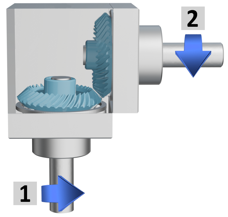
2 outputs, same rotation direction |
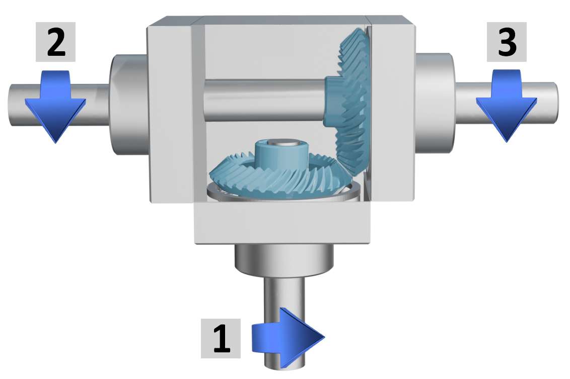
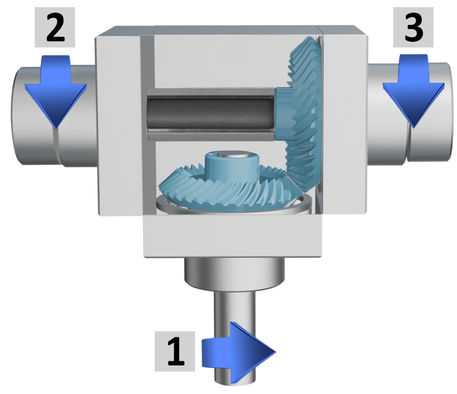
3 outputs, same rotation direction |
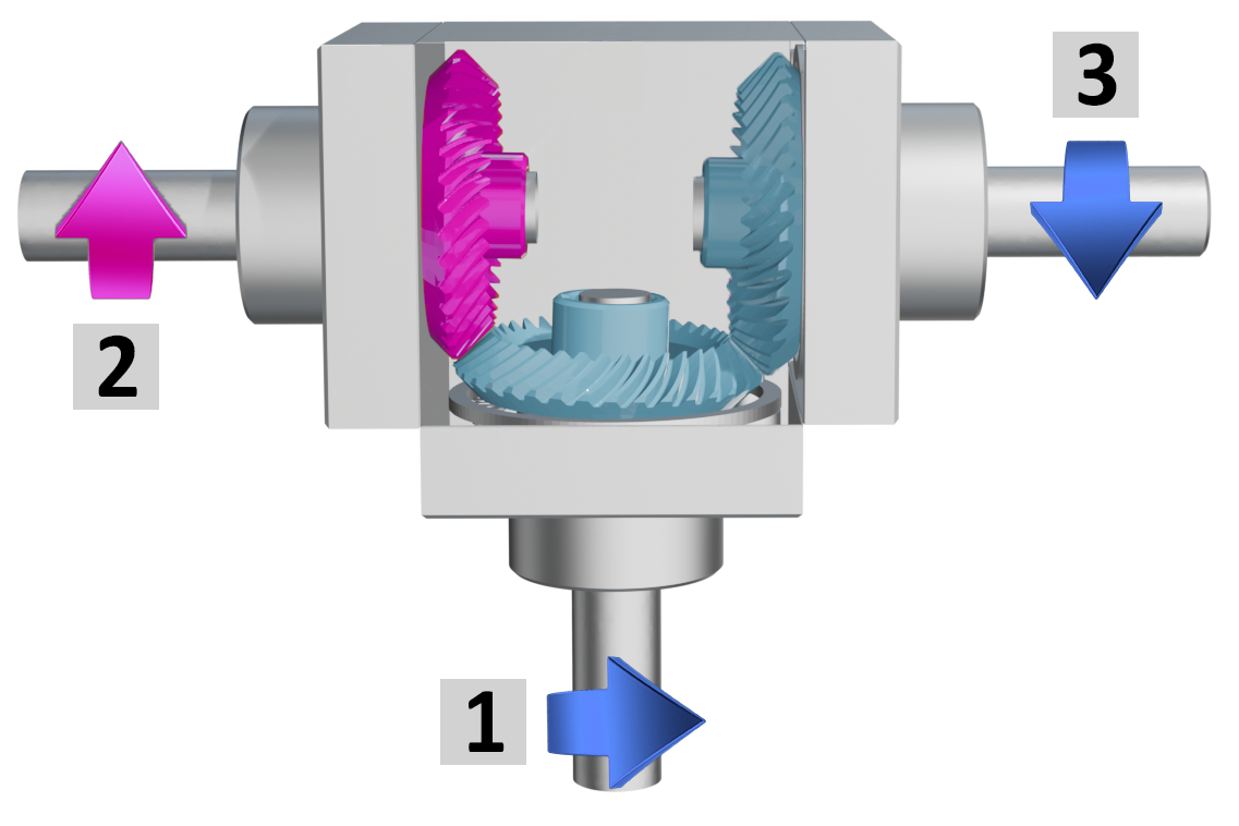
3 outputs, 1 with opposite rotation directions |
| ⟪D⟫ | ⟪E⟫ |
|
|
|
|
3 outputs, 2 with through hollow shafts, same rotation direction |
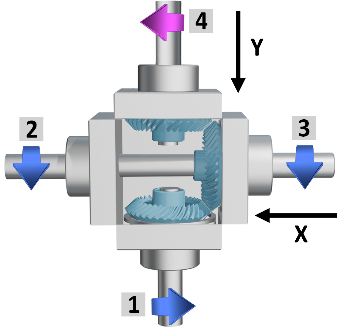
4 outputs, same rotation direction on axis X, opposite on axis Y |
|
|
|
|
OUTPUT SHAFT IDENTIFICATION |
Tab.2 |
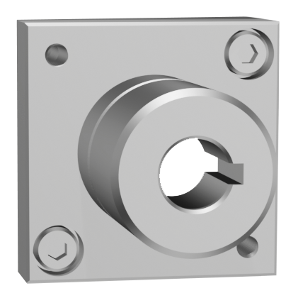
| AVAILABLE OUTPUT SHAFTS | ||||||||
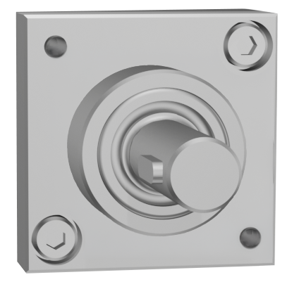
| male = M |
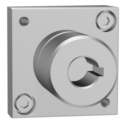
female blind = F |
through female = F |
||||||
 |
 |
 |
||||||
|
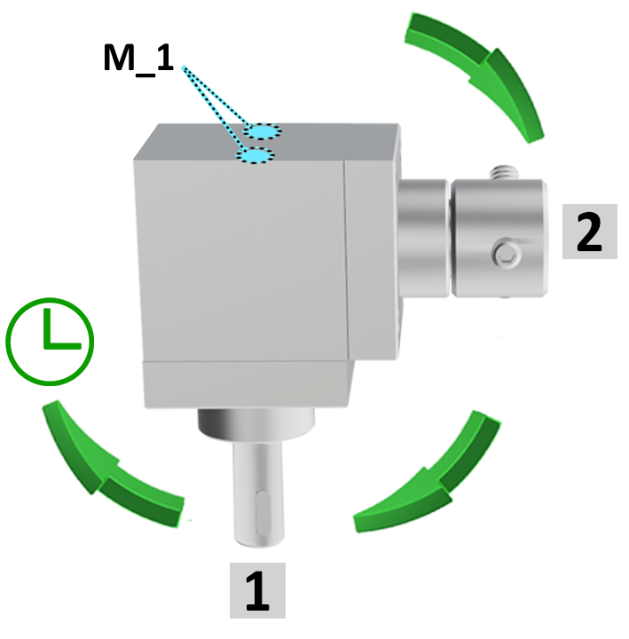
Example with 2 outputs |
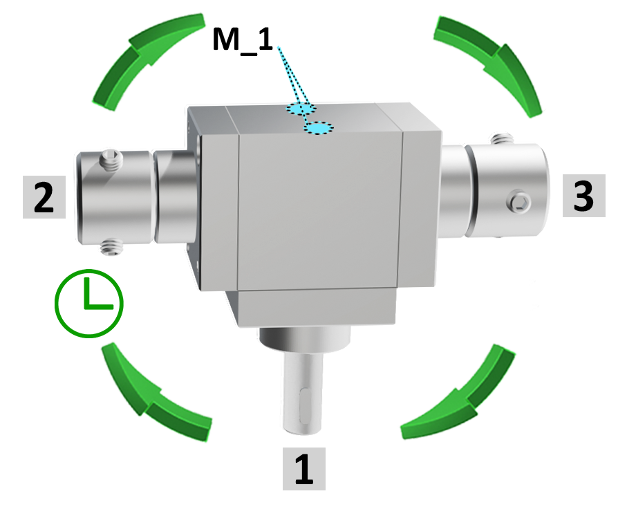
Example with 3 outputs |
 |
 |
|
|
|
|
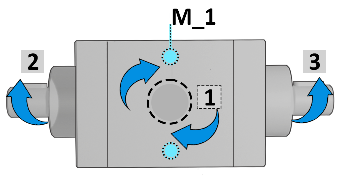
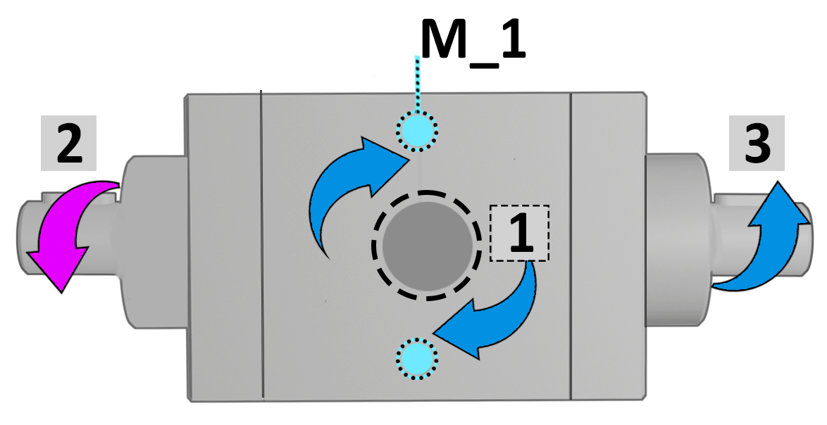
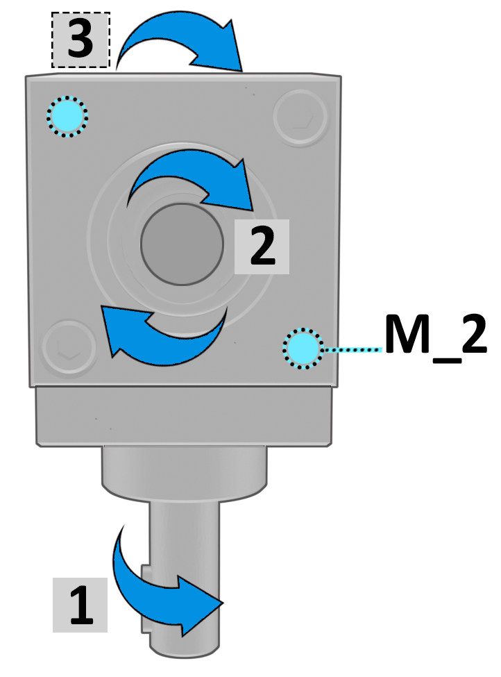
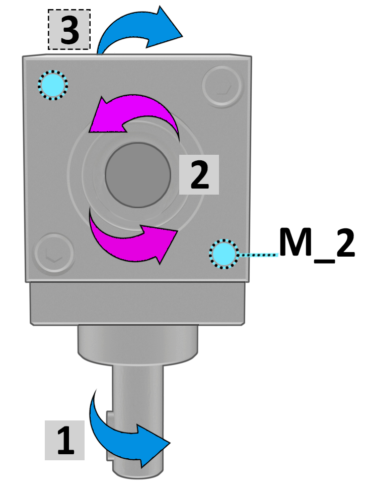
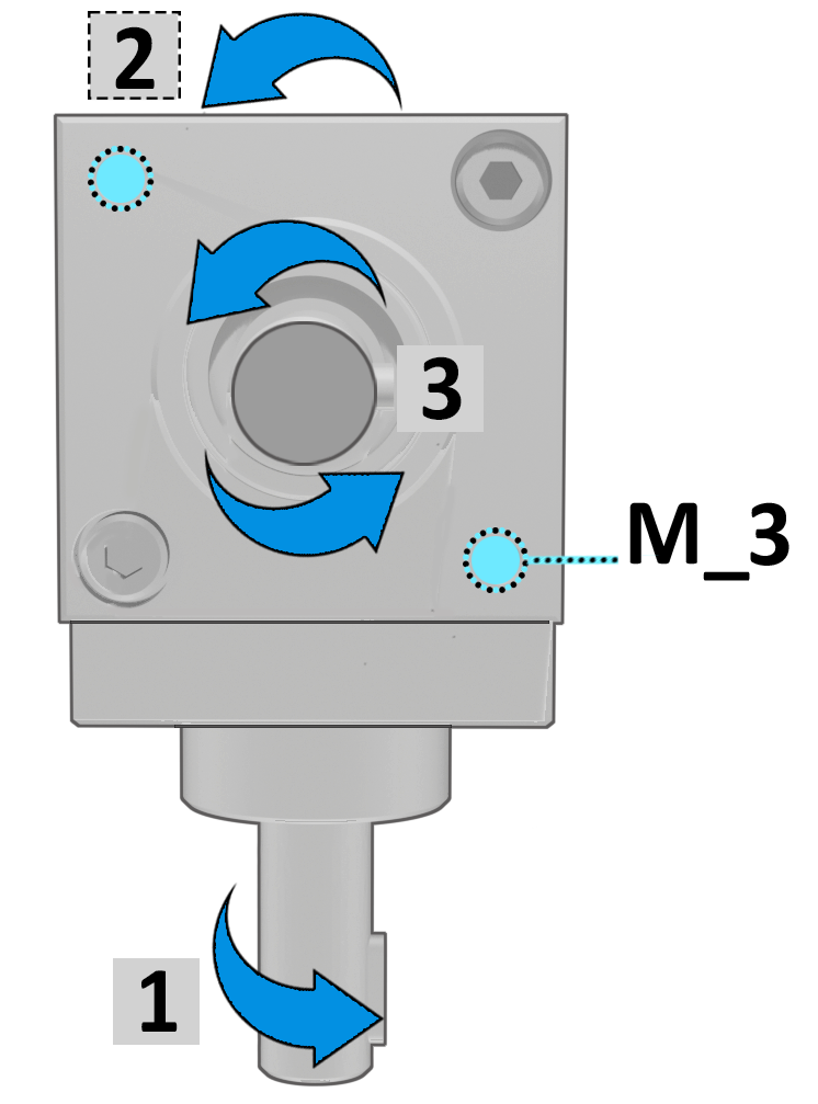
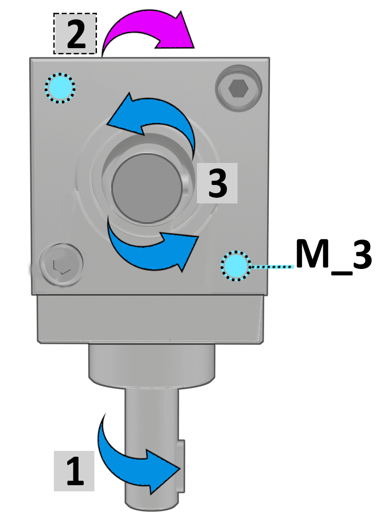
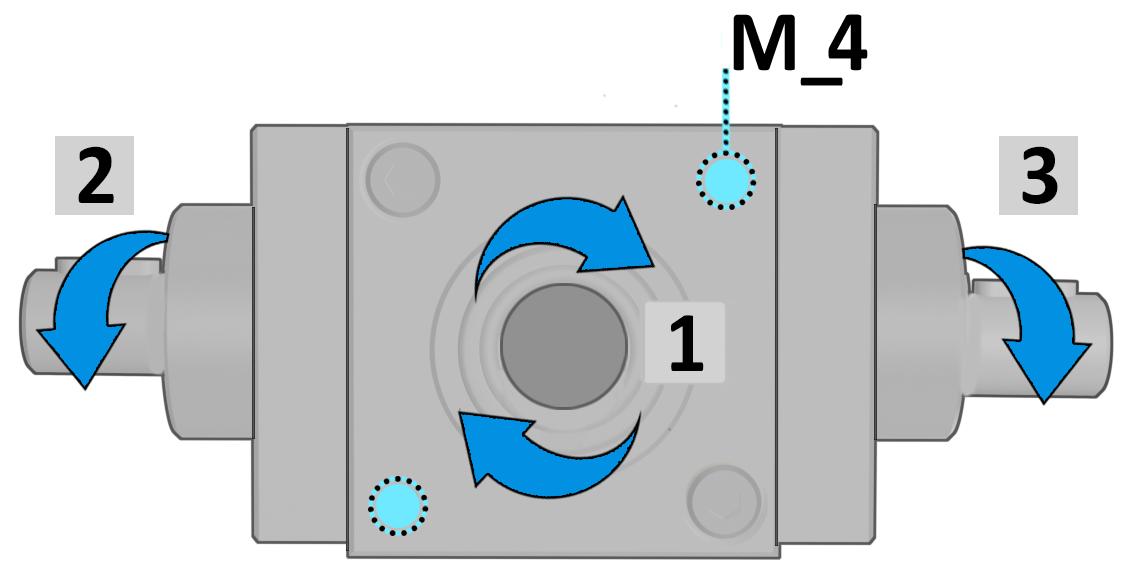
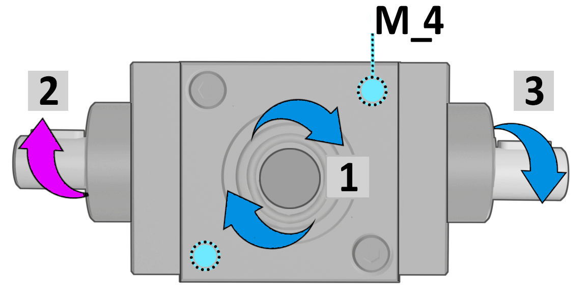
Shaft 1 is always shown on the side opposite the M_1 fixing bores and serves as the reference for determining: |
|
|
● the configuration |
|
|
● the direction of rotation |
|
|
● the gear ratio |
|
|
By convention, Shaft 1is shown rotating clockwise. The others shaft are defined following the clockwise direction. |
|
|
AVAILABLE TRANSMISSION RATIOS |
Tab.3 |
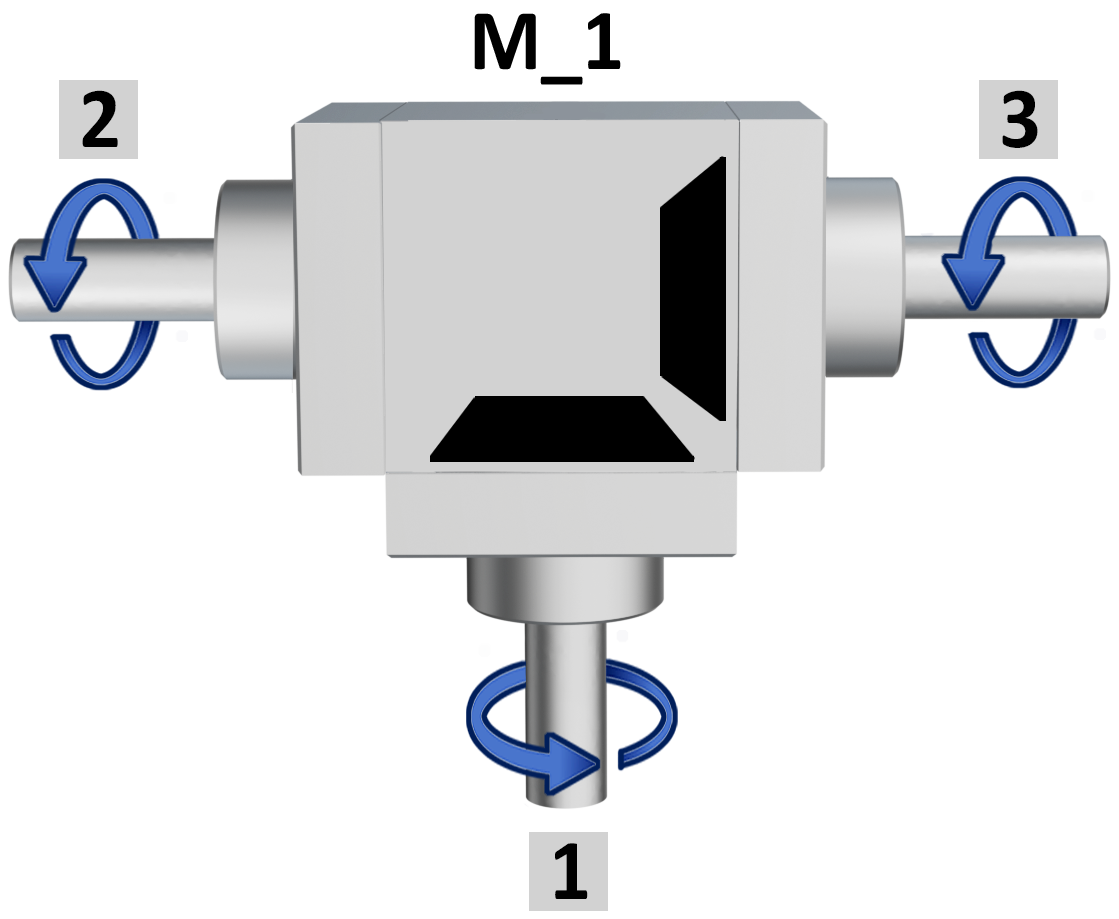
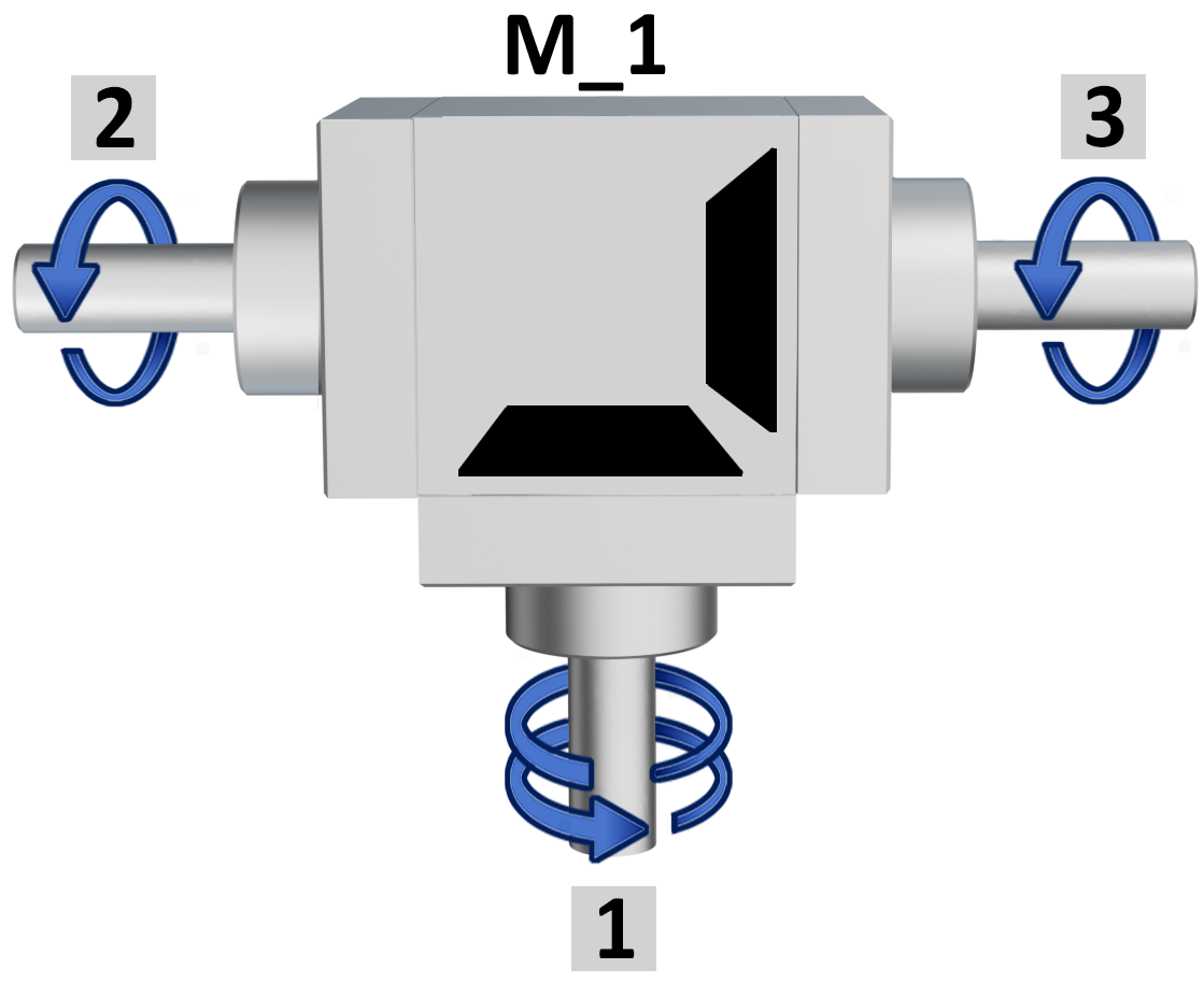
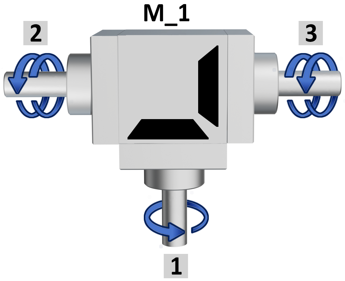
 The ratio is determined by the shaft1always shown on the opposite side of the fixing bores M_1. The ratio is determined by the shaft1always shown on the opposite side of the fixing bores M_1. |
||
| Ratio 1/1 | Ratio 1/2 | Ratio 2/1 |
 |
 |
 |
|
Example |
Example |
Example |
| Shaft 1 = 10 rpm | Shaft 1 = 10 rpm | Shaft 1 = 5 rpm |
| Shafts 2-3 = 10 rpm | Shafts 2-3 = 5 rpm | Shafts 2-3 = 10 rpm |
| not available in version D | ||
| M_ FIXING POSITIONS | Tab.4 |
|
|
| M_1 = top view. 0° | M_2 = right side view 90° | |||
 |
 |
+90° →DX |
 |
 |
| same rotation | opposite rotation | same rotation | opposite rotation | |
|
↑ +90° |
+90° ↓ |
|||
| M_3 = left side view 270° | M_4 = bottom view 180° | |||
 |
 |
+90° ← SX |
|
|
| same rotation | opposite rotation | same rotation | opposite rotation | |
| GREASE NIPPLE POSITION | Tab.5 |
|
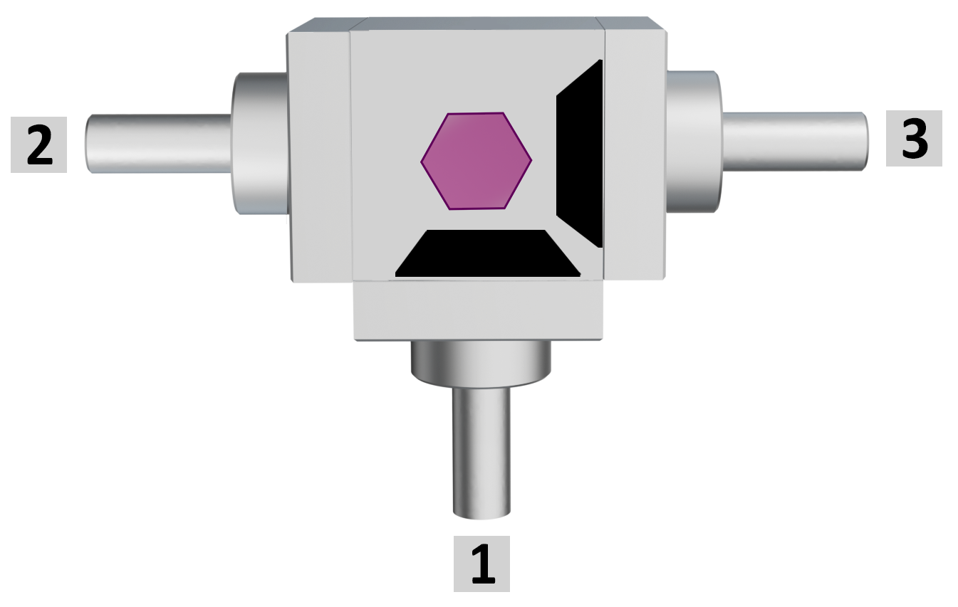
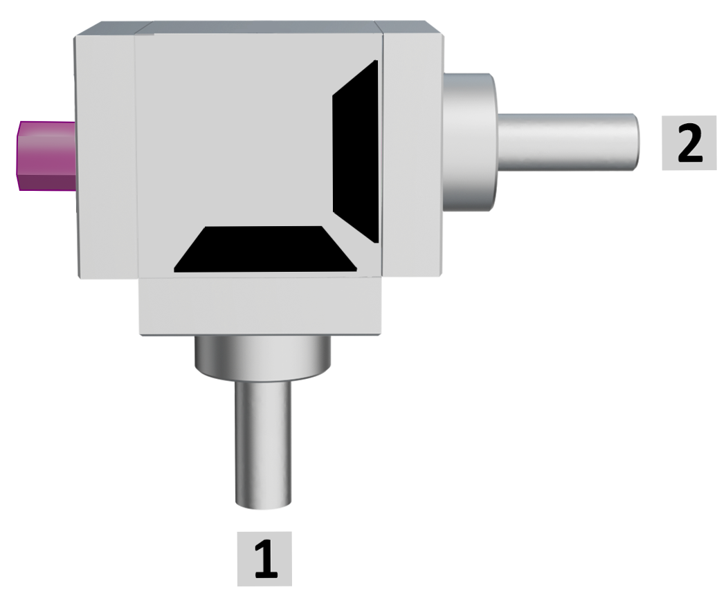
Gearboxes with 2 shafts |
Gearboxes with 3 shafts |
|
|
|
 |
|
|
For model 66/22 and 66/8 only: recommended for demanding conditions or extended service life. Periodically replenish the lubricant as instructed by our Technical Department. Supplied in the standard position shown; other positions on request. |
||
| REPRESENTATION OF LOADS | Tab.6 |
|
«B» |
«D» |
|
 |
 |
|
| Fr = radial load acts in a perpendicular direction to the shaft Fa = axial load, in pull or push) acts in the same direction of the shaft T = torque |
||
|
|
||
GENERAL INFO_66 

Click here to download
GENERAL INFO_66 
Click here to download
GENERAL INFO_66 

Click here to download