
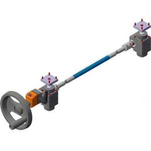
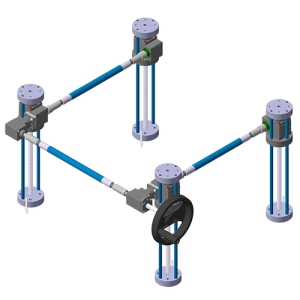
ASR
Semi-rigid shafts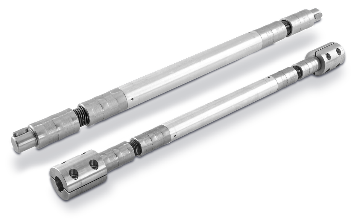
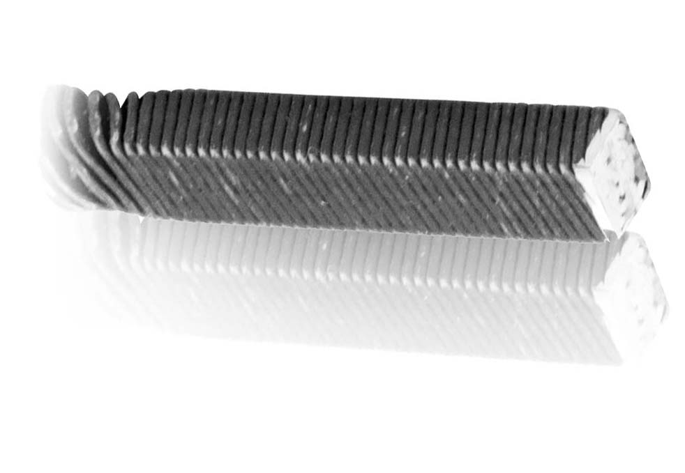
ASR semi-rigid shafts provide an economical and practical solution to trasnfer the rotary movement between two aligned elements ensuring an optimal and long-lasting efficiency of motion transmission in case of slight misalignments due to construction or installation.
➤ Rigid protection cover made of aluminium.
• Terminals made of stainless steel AISI 303, available models (☛see section "Accessories"):
| - cylindrical solid CL | - cylindrical female CF |
 |
| - cylindrical male CM | - 2 piece cylindrical male CMB |
|
|
 |

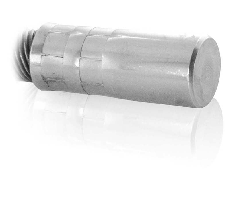
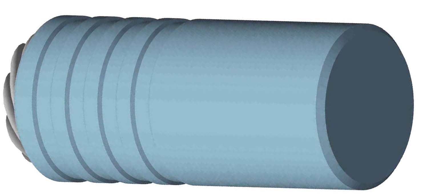
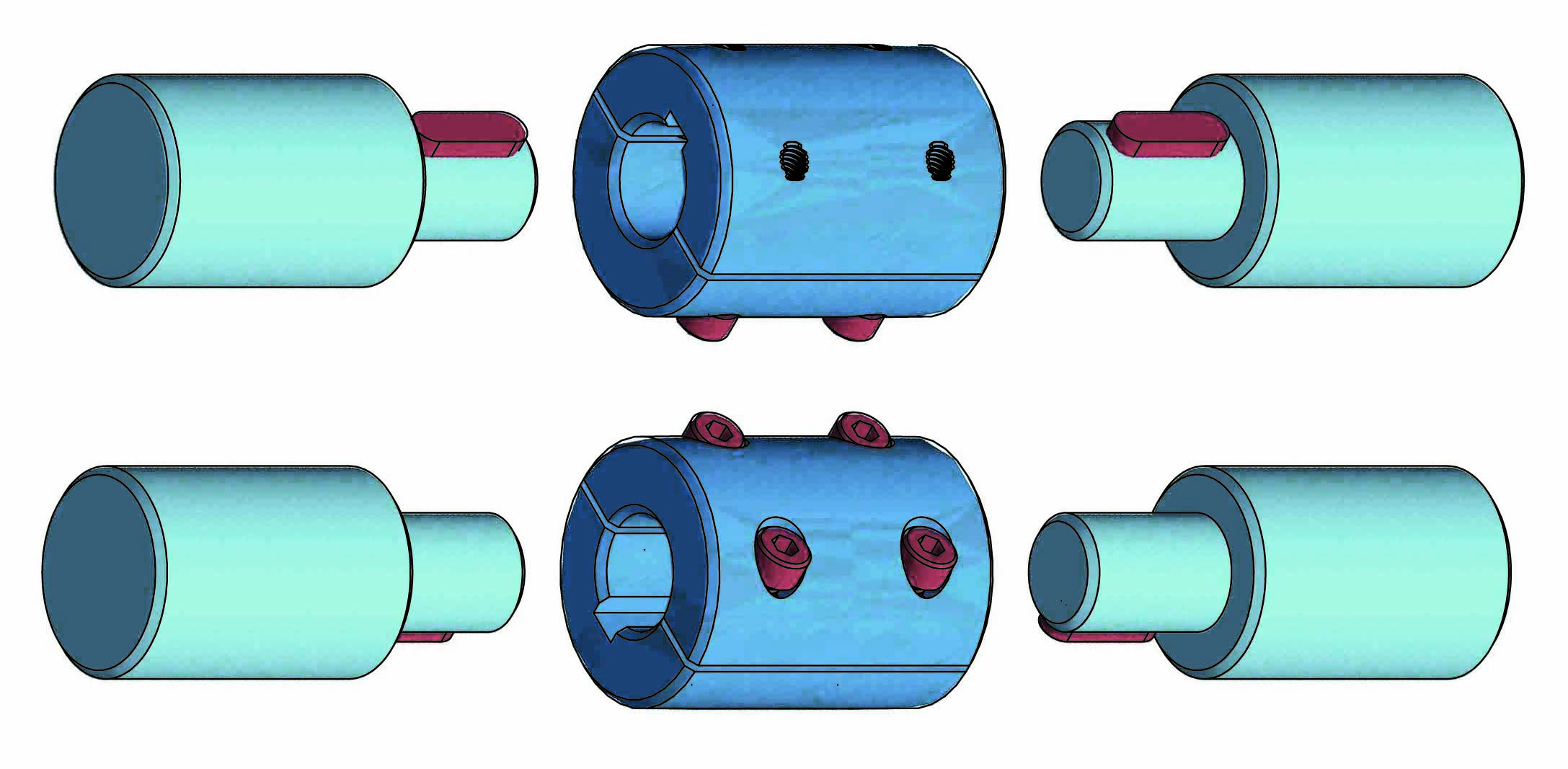
Photogallery
| SEMI-RIGID SHAFT <ASR> |

| * for the ASR model the flexible shafts are 2 (10mm each) |
| DIMENSIONS TABLE | ||
| VERSION | FLEXIBLE SHAFT | RIGID SHAFT |
| Ø A | Ø B | |
| ASR6 | 6 | 12 |
| ASR10 | 10 | 14 |
| ASR15 | 15 | 20 |
| ASR20 | 20 | 25 |


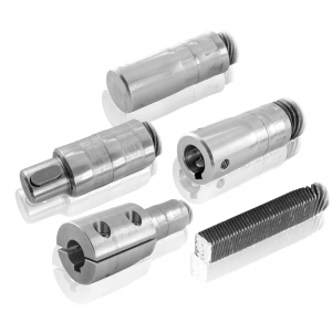
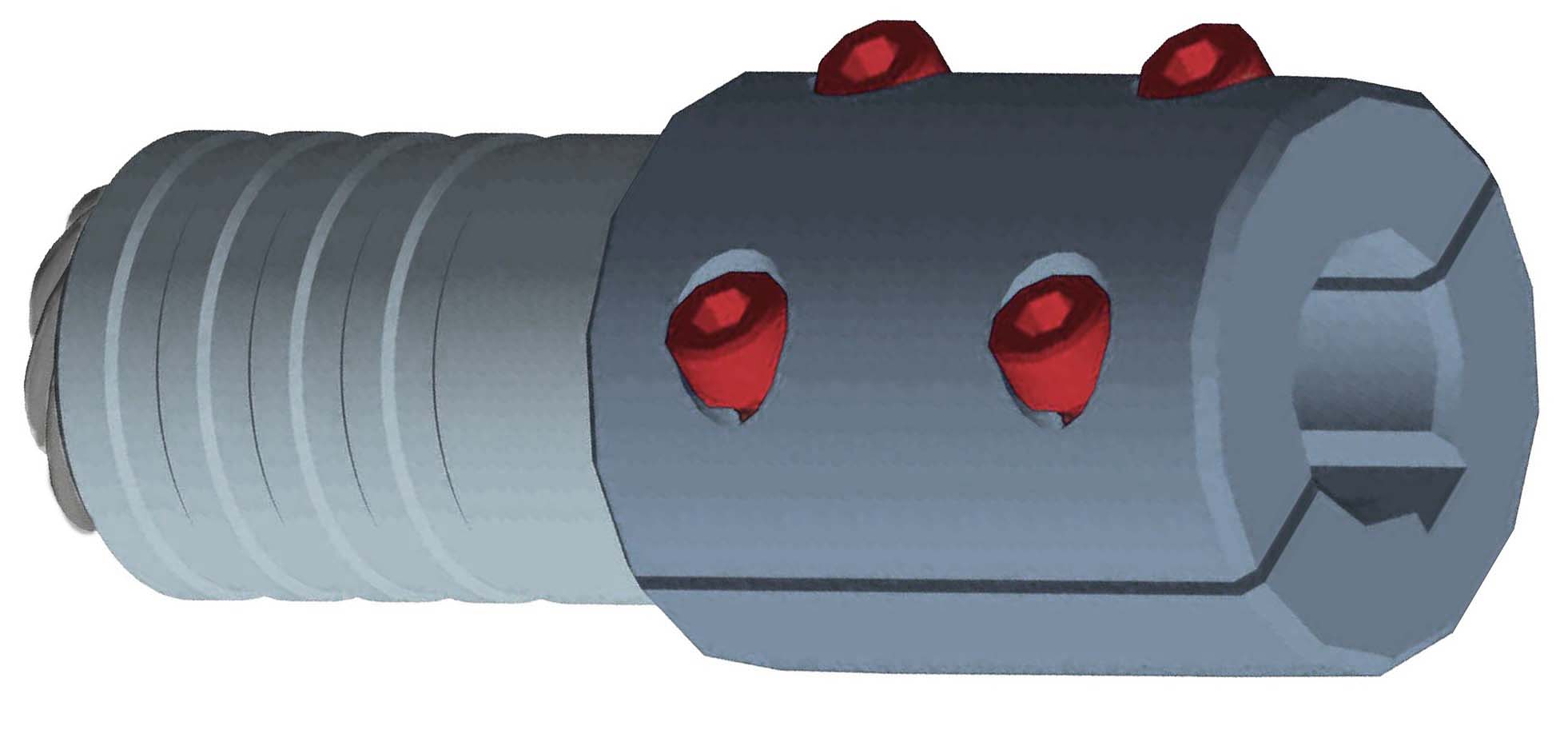
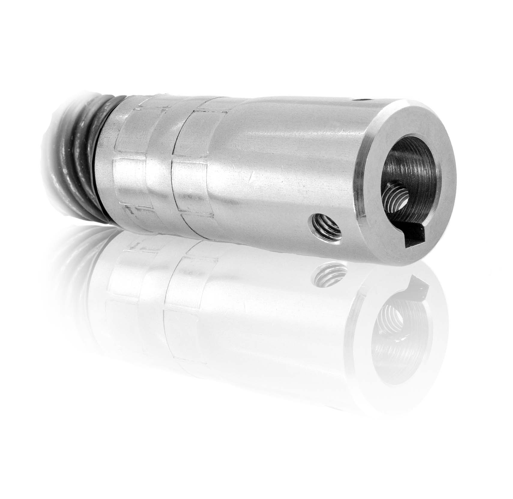
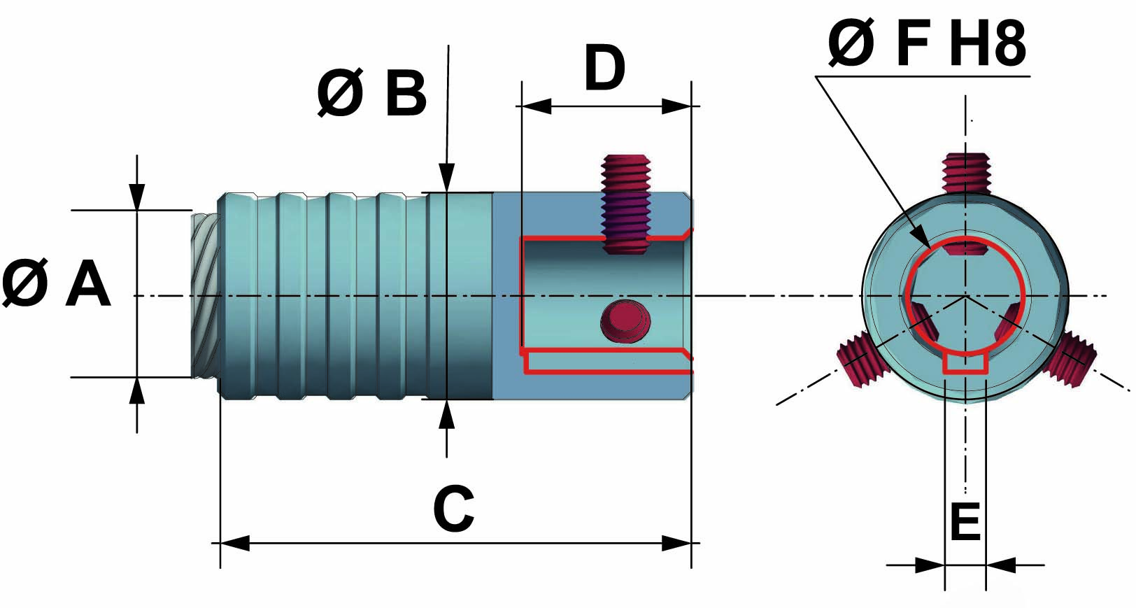
FIXING TERMINALS
made of stainless steel AISI 303, available models:
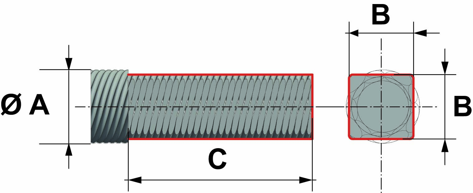
| Q = square |
 |
| |
|
 |
|
| FLEXIBLE SHAFT | EXTERNAL SQUARE | TOTAL LENGTH |
| Ø A | Ø B | C |
| 6 | 5 | 30 |
| 8 | 6.5 | 35 |
| 10 | 8.5 | 40 |
| 12 | 10 | 40 |
| 15 | 13 | 45 |
| 20 | 17.5 | 45 |
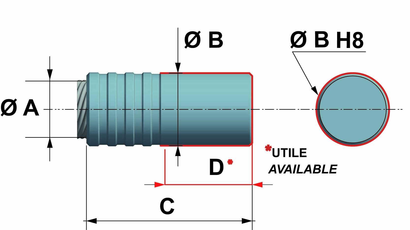
| CL = cylindrical solid |
 |
 |
|
 |
|
| FLEXIBLE SHAFT | EXTERNAL DIAMETER | TOTAL LENGTH | AVAILABLE LENGTH |
| Ø A | Ø B | C | D |
| 6 | 10 | 28 | 12 |
| 8 | 12 | 38 | 16 |
| 10 | 14 | 44 | 20 |
| 12 | 16 | 48 | 22 |
| 15 | 20 | 50 | 25 |
| 20 | 25 | 57 | 30 |
| CF = cylindrical female |
 |
 |
|
 |
|
| FLEXIBLE SHAFT | EXTERNAL DIAMETER | TOTAL LENGTH | BORE DEPTH | KEYWAY | BORE |
| Ø A | Ø B | C | D | E | Ø F |
| 6 | 12 | 28 | 10 | = | 6 |
| 8 | 16 | 38 | 15 | = | 8 |
| 10 | 16 | 44 | 15 | = | 8 |
| 12 | 20 | 48 | 16 | 3 | 10 |
| 15 | 20 | 50 | 16 | 3 | 10 |
| 20 | 25 | 57 | 20 | 5 | 14 |
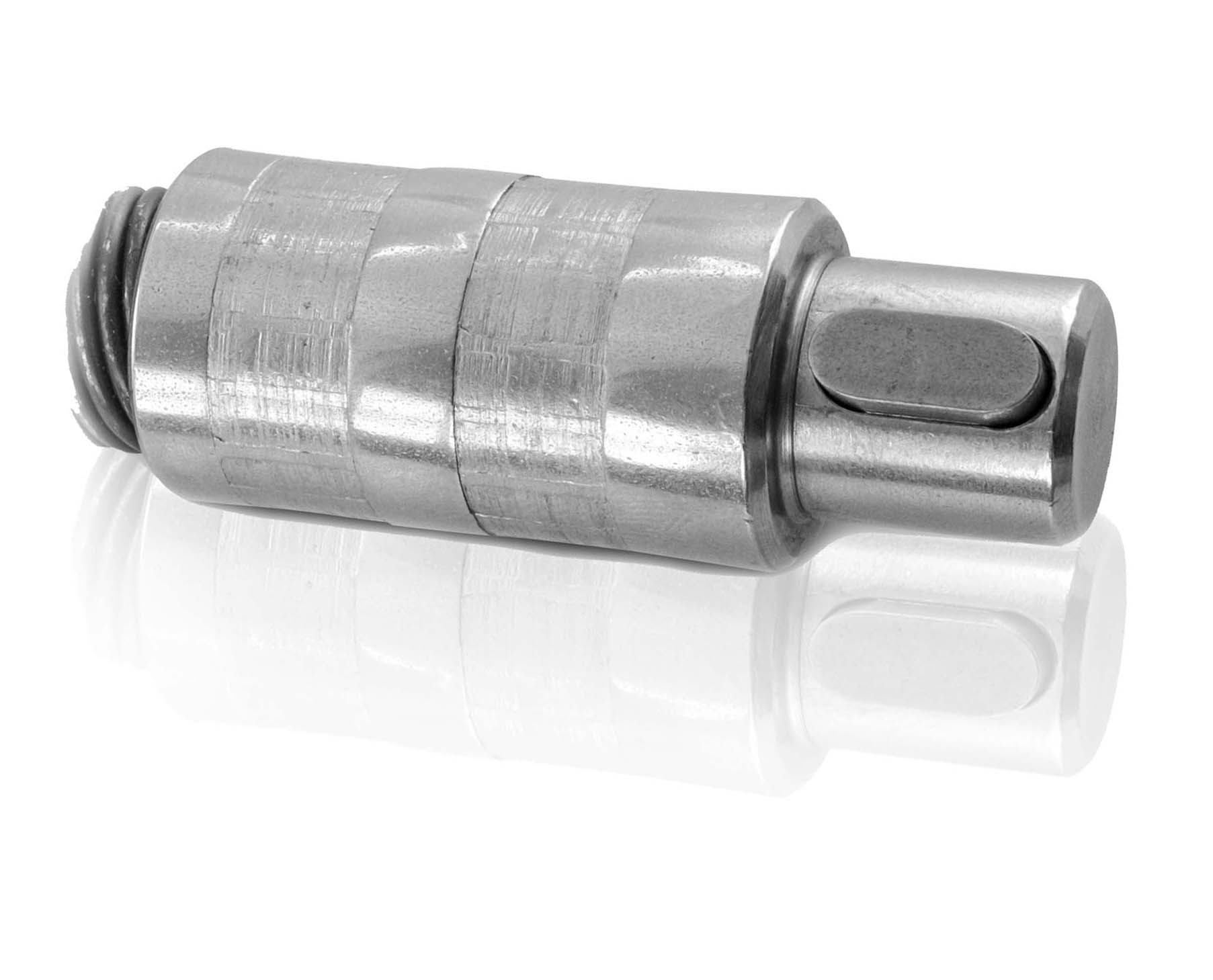
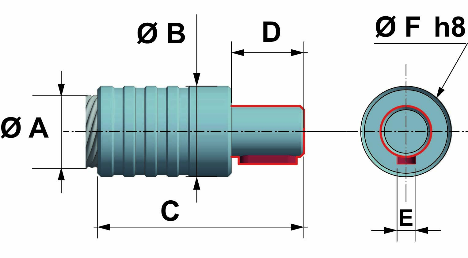
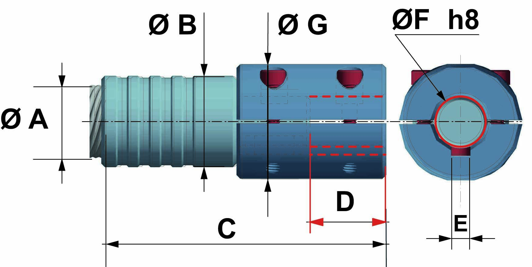
| CM = cylindrical male |
 |
 |
|
 |
|
| FLEXIBLE SHAFT | EXTERNAL DIAMETER | TOTAL LENGHT | AVAILABLE LENGTH | KEYWAY | MALE DIAMETER |
| Ø A | Ø B | C | D | E | Ø F |
| 6 | 10 | 28 | 10 | = | 6 |
| 8 | 12 | 38 | 14 | = | 8 |
| 10 | 14 | 44 | 14 | = | 8 |
| 12 | 16 | 48 | 15 | 3 | 10 |
| 15 | 20 | 50 | 15 | 3 | 10 |
| 15 | 20 | 50 | 15 | 5 | 14* |
| 20 | 25 | 57 | 20 | 5 | 14 |
* optional
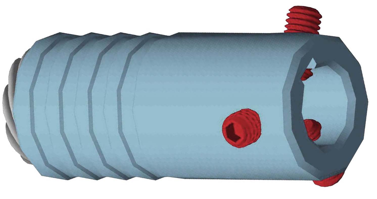
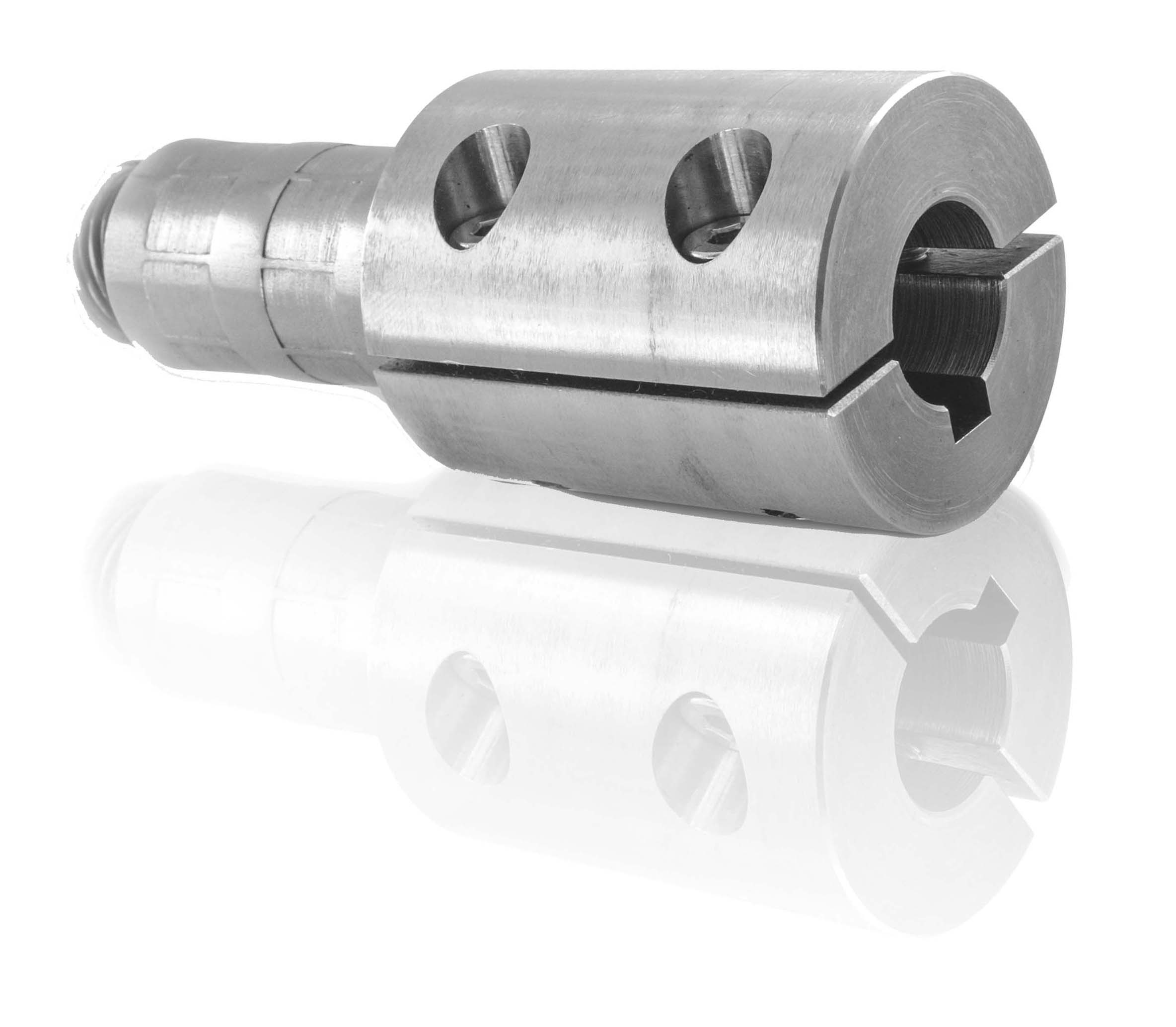
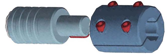
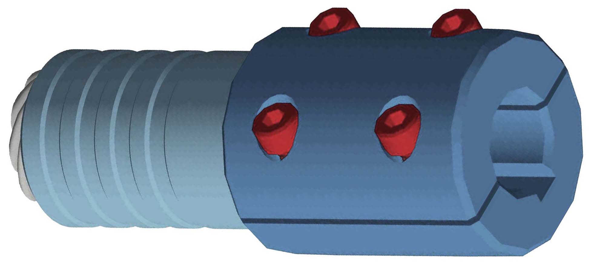
| CMB = 2 piece connection bushing |
 |
 |
|
 |
|
 |
|
| FLEXIBLE SHAFT | EXTERNAL DIAMETER | TOTAL LENGHT | AVAILABLE LENGTH | KEYWAY | BORE | EXTERNAL BUSHING |
| Ø A | Ø B | C | D | E | Ø F | Ø G |
| 6 | 10 | 28 | 10 | = | 6 | 14 |
| 8 | 12 | 38 | 14 | = | 8 | 22 |
| 10 | 14 | 44 | 14 | = | 8 | 22 |
| 12 | 16 | 48 | 15 | 3 | 10 | 24 |
| 15 | 20 | 50 | 15 | 3 | 10 | 24 |
| 15 | 20 | 50 | 15 | 5 | 14* | 32* |
| 20 | 25 | 57 | 20 | 5 | 14 | 32 |
* optional

COUPLING BUSHES 2 piece bushing to couple gearboxes and shafts.
Available bores Ø: 6 - 8 -10 -14.
➜ for more complete information, see BT
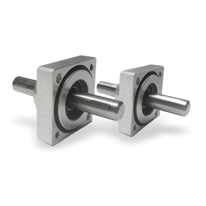
Flanged supports with extension shaft for coupling with position indicators.
➜ for more complete information, see Flanged supports
Richiedi l'accesso
| EFFICIENCY TABLE | ||||
| VERSION | TORSION | MIN. BENDING RADIUS | TORQUE | WEIGHT |
| (°) | mm | Nm | gr | |
| ASR6 | 80 | 70 | 3 | 600 |
| ASR10 | 70 | 130 | 7.5 | 750 |
| ASR15 | 28 | 300 | 12 | 2050 |
| ASR20 | 18 | 400 | 18.5 | 3400 |
| The data refers to length L=1000mm |
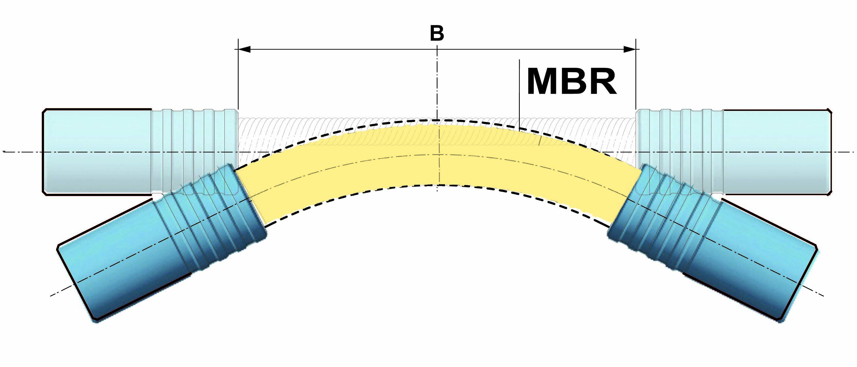
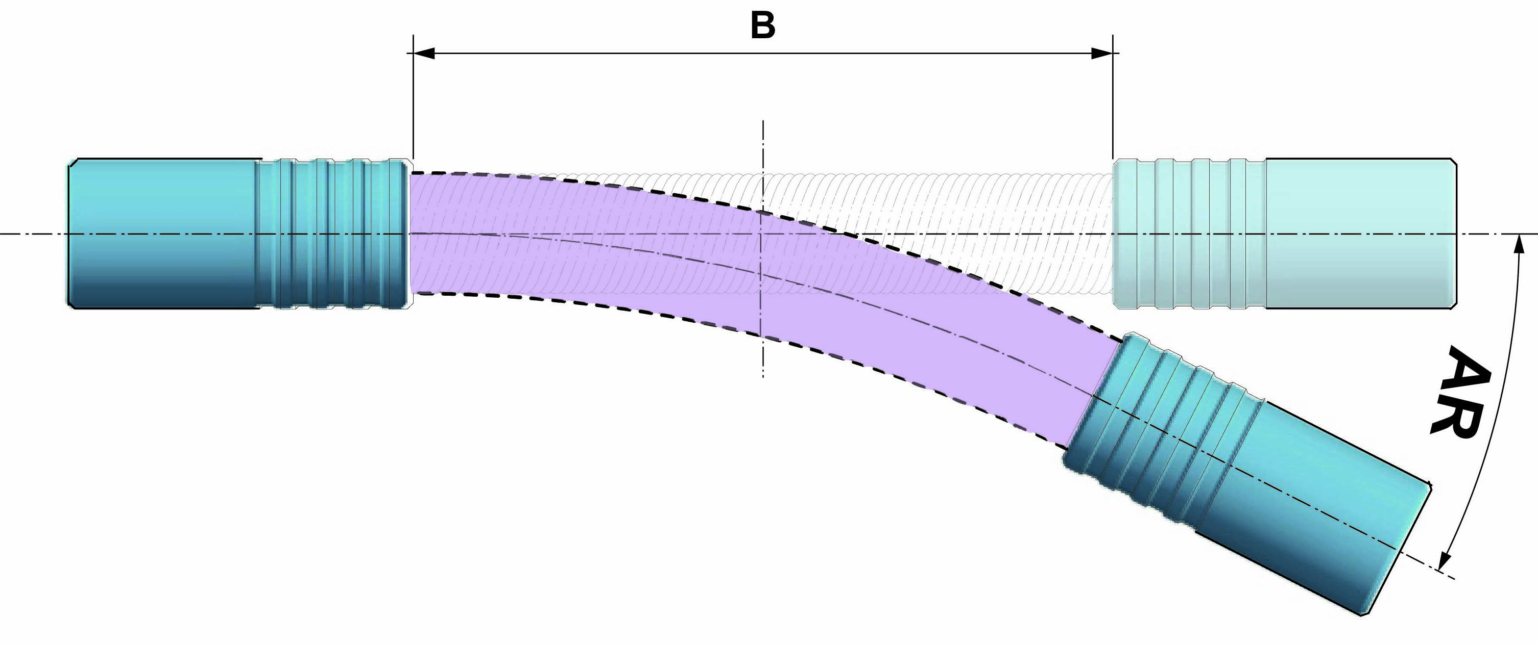
| FLEXIBILITY AND BENDING RADIUS |
Flexibility and minimum bending radius are important factors especially if the shaft is exposed to severe bending during its use.
☛ It is necessary to make sure that the lowest bending radius applied to the transmission is greater than its minimum radius of curvature. If during use the shaft reaches a bending radius which is below the minimum bending radius, the unit can be crushed, or deformed or excessivley stressed, and thus reduce its strength and / or durability or even cause it to fail.
Up to this radius it is possible to bend the transmission during operation without damaging or excessive reduction in its lifetime.
| BENDING RADIUS |
| WORKING ANGLE |
| MISALIGNEMENT |
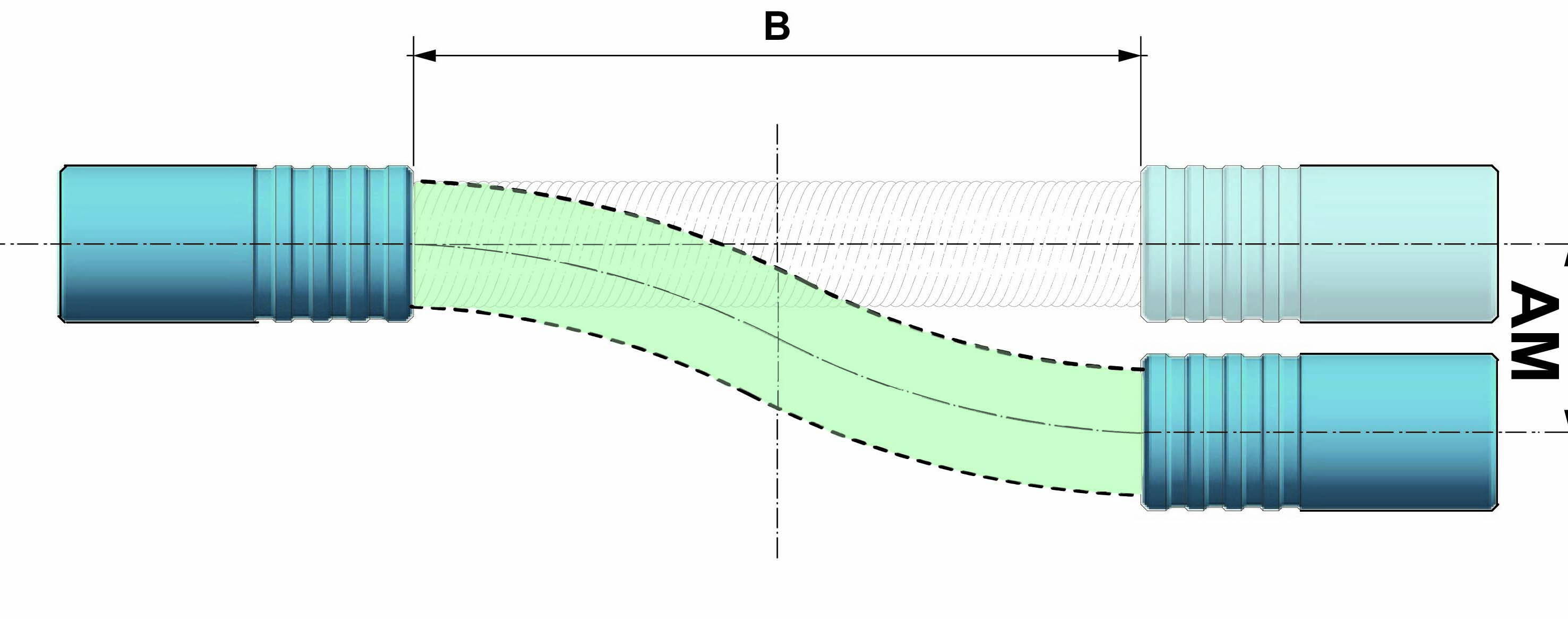
| FLEXIBILITY AND BENDING RADIUS | ||||
| Ø | B | MBR | AR | AM |
| FLEXIBLE SHAFT | LENGTH OF FLEXIBLE SHAFT* mm | BENDING RADIUS mm | WORKING ANGLE (°) | MISALIGNEMENT mm |
| 6 | 10 | 70 | 4.09 | 0.36 |
| 10 | 10 | 130 | 2.20 | 0.20 |
| 15 | 10 | 300 | 0.95 | 0.08 |
| 20 | 10 | 400 | 0.72 | 0.06 |
| * for the AR model the flexible shafts are 2 (10mm each) |
| EFFICIENCY TABLE |
| MAX. TORQUE / ANGLE | |||
| Ø | B | T | φ |
| FLEXIBLE SHAFT Ø | LENGTH OF FLEXIBLE SHAFT* mm | MAX. WORKING TORQUE Nm | ROTATION ANGLE (°) |
| 6 | 10 | 3.0 | 0.79 |
| 10 | 10 | 7.5 | 0.74 |
| 15 | 10 | 12.5 | 0.30 |
| 20 | 10 | 18.5 | 0.17 |
| MAX. TORQUE ANGLE with discording winding | |||
| Ø | B | T | φ |
| FLEXIBLE SHAFT Ø | LENGTH OF FLEXIBLE SHAFT* mm | MAX. WORKING TORQUE Nm | ROTATION ANGLE (°) with discording winding |
| 6 | 10 | 3.0 | 0.79 |
| 10 | 10 | 7.5 | 0.74 |
| 15 | 10 | 8.75 | 0.30 |
| 20 | 10 | 12.95 | 0.17 |
| * for the AR model the flexible shafts are 2 (10mm each) |


