RINV-OP62
Angular flanged gearbox
The RINV-OP62 is a flanged angular gearbox that, combined with a position indicator type “OP2” allows a numeric adjustment, angular or linear, even if the shaft is in an uncomfortable position.
• Several orientations and connection possibilities.
• Available with 1:1 ratio.
• Maximum output torque 3,8 Nm.
• Aluminium case, anodized. Steel shafts. Steel bevel gears, surface-hardened (Pronox).
• Minimum angular backlash, minimum axial backlash.
• Movements on ball-bearings, water-proof.
• Radial load 7,5 kg - axial load 0,7 kg
• Weight 80g.
| RINV-OP62 |
|
|
|
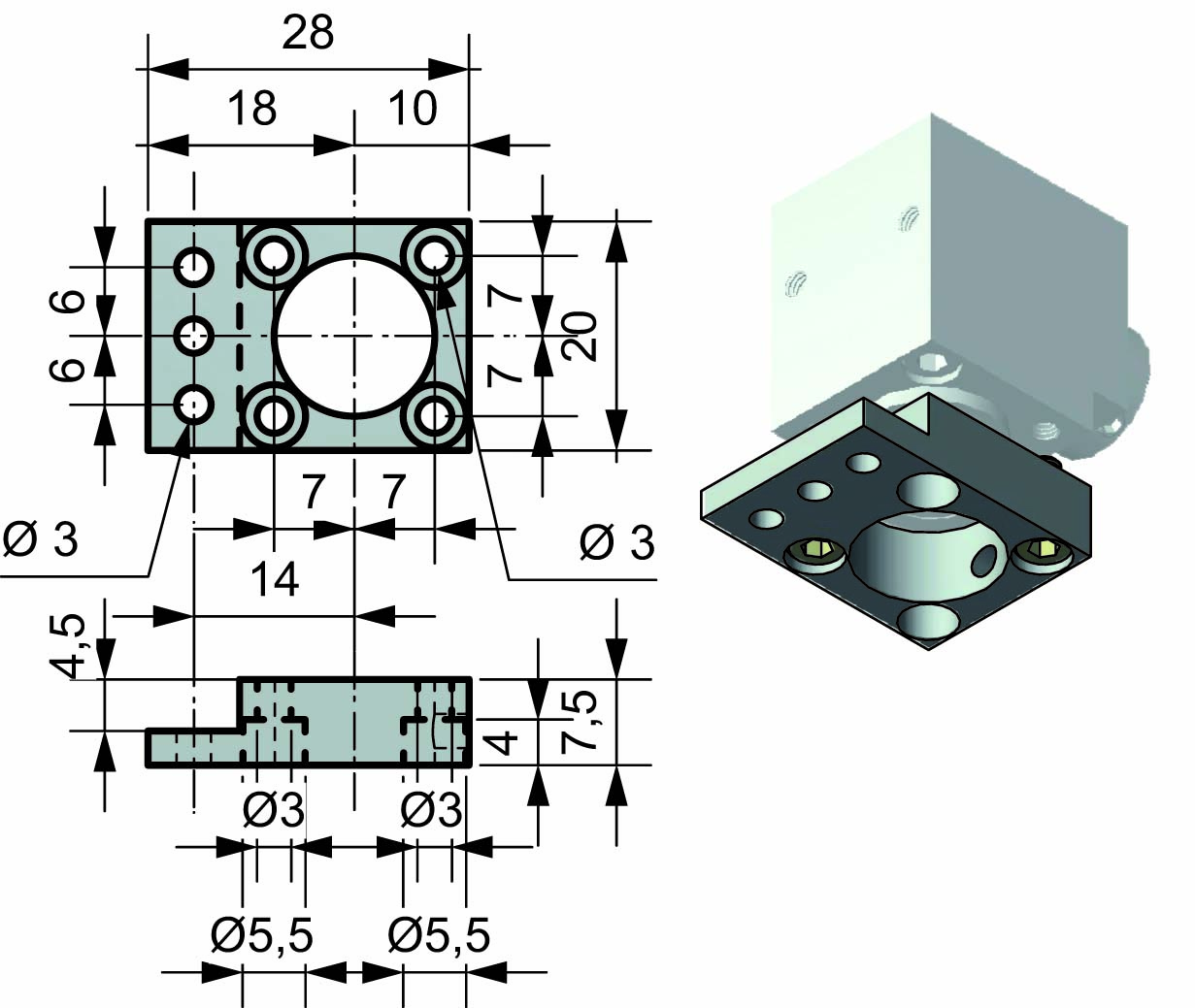
MACHINE FLANGE |
 |
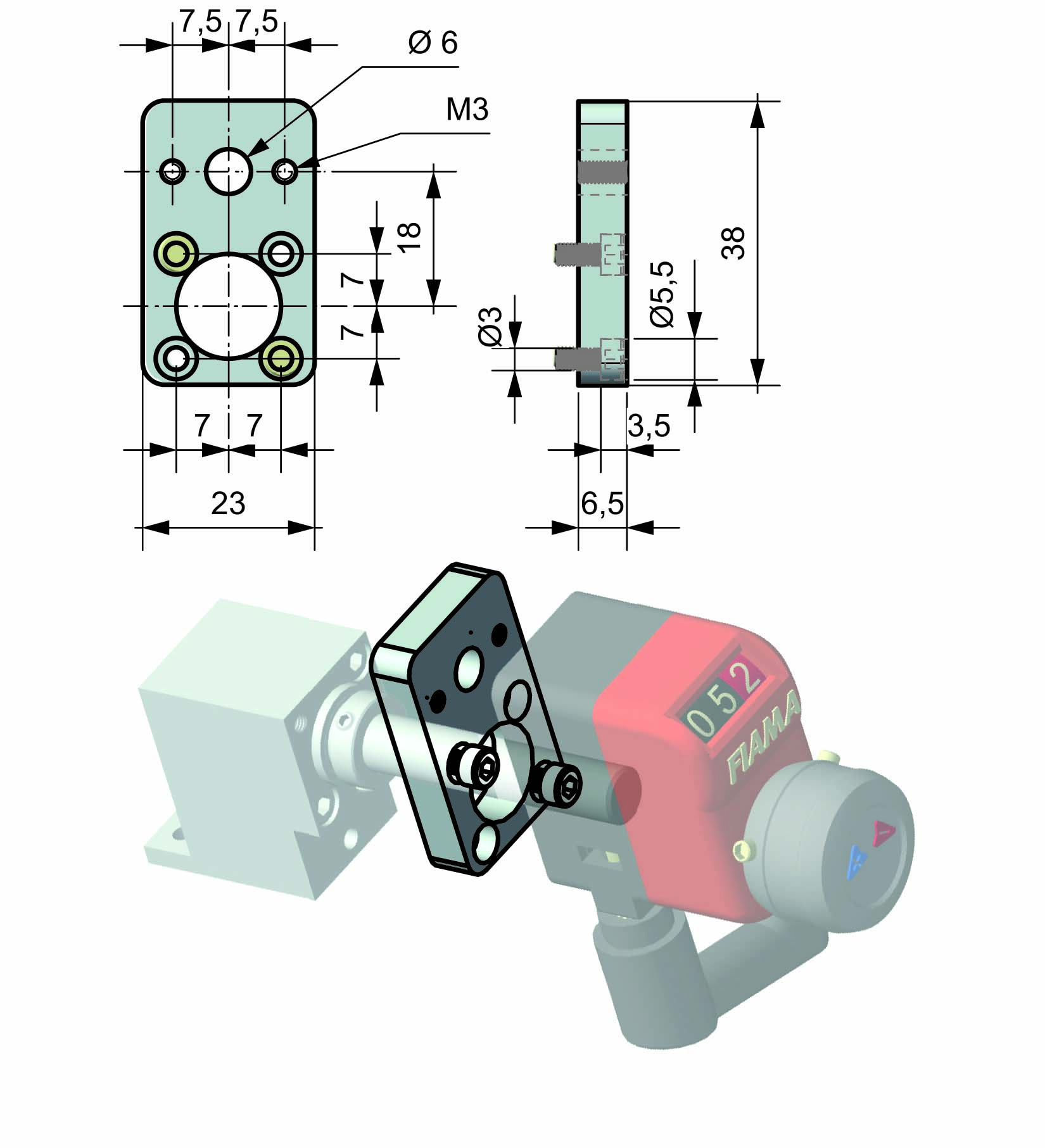
| OP FLANGE |
 |
| EXAMPLES OF MOUNTING POSITIONS | |
 |
 |
 |
 |
The RINV-OP is supplied standard as per overall drawing. To change the mounting position of the two flanges (flange on OP side and fixing flangeon machine side),remove the two fixing screws, turn the flange in desired position, and fix the two screws.To fix the machine side, insert shaft into the hollow shaft of the RINV-OP, fix the flange on fix part of the machine then lock the fixing screws through the bore of the flange.

Control handwheel with folding handle, thermoplastic material, steel bush.
➜ for more complete information, see V.R
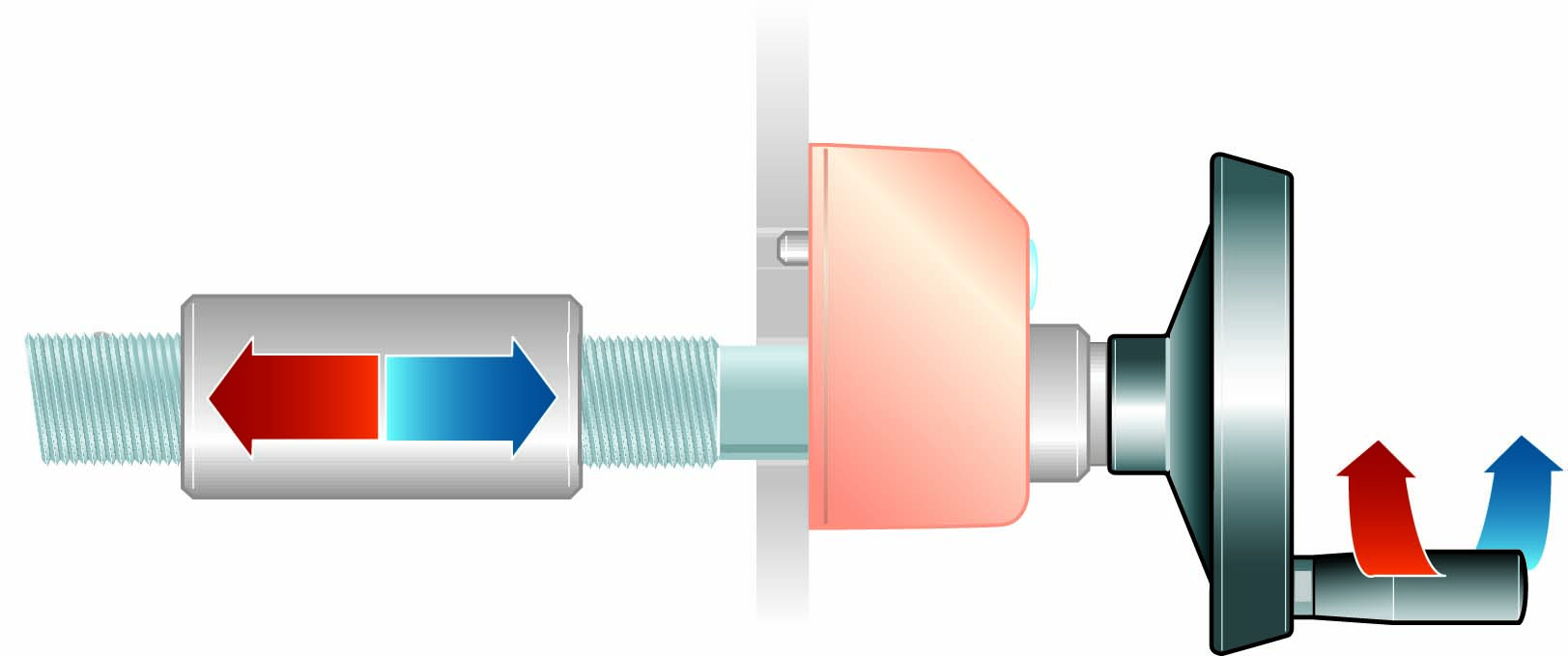

Crank handle with folding handle in thermoplastic material, steel bush.
➜ for more complete information, see V.M

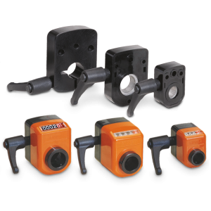
With the shaft block flange on the OP2, OP3, OP6, OP7, OP5, OP9 indicator as a compact unity, we obtain a safe blocking of the drive shaft.
➜ for more complete information, see FL-B

• 3 digits counter (standard red digit indicates decimals; on request 2 red digits for hundredths or 3 black digits for mm). Reading until 999. Digit height 6 mm
• Particularly suitable for little adjustments in small spaces.
• Standard shaft bore Ø8, Ø10 or Ø12.
➜ for more complete information, see OP2
Richiedi l'accesso
RADIAL AND AXIAL LOAD
The loads are generated by the items connected to the gearbox and can be created for example by the pull of belt drives, accelerations and decelerations, structural misalignments, vibrations, shocks, etc.
The loads acting on the shafts can be of two types: radial ‹Fr› (radial force) and axial ‹Fa› (axial force), referred to the axis of the shaft; when ordering specify whether the axial load is pull or push type.
Fr = radial load
is the load acting in perpendicular direction to the shaft/axis
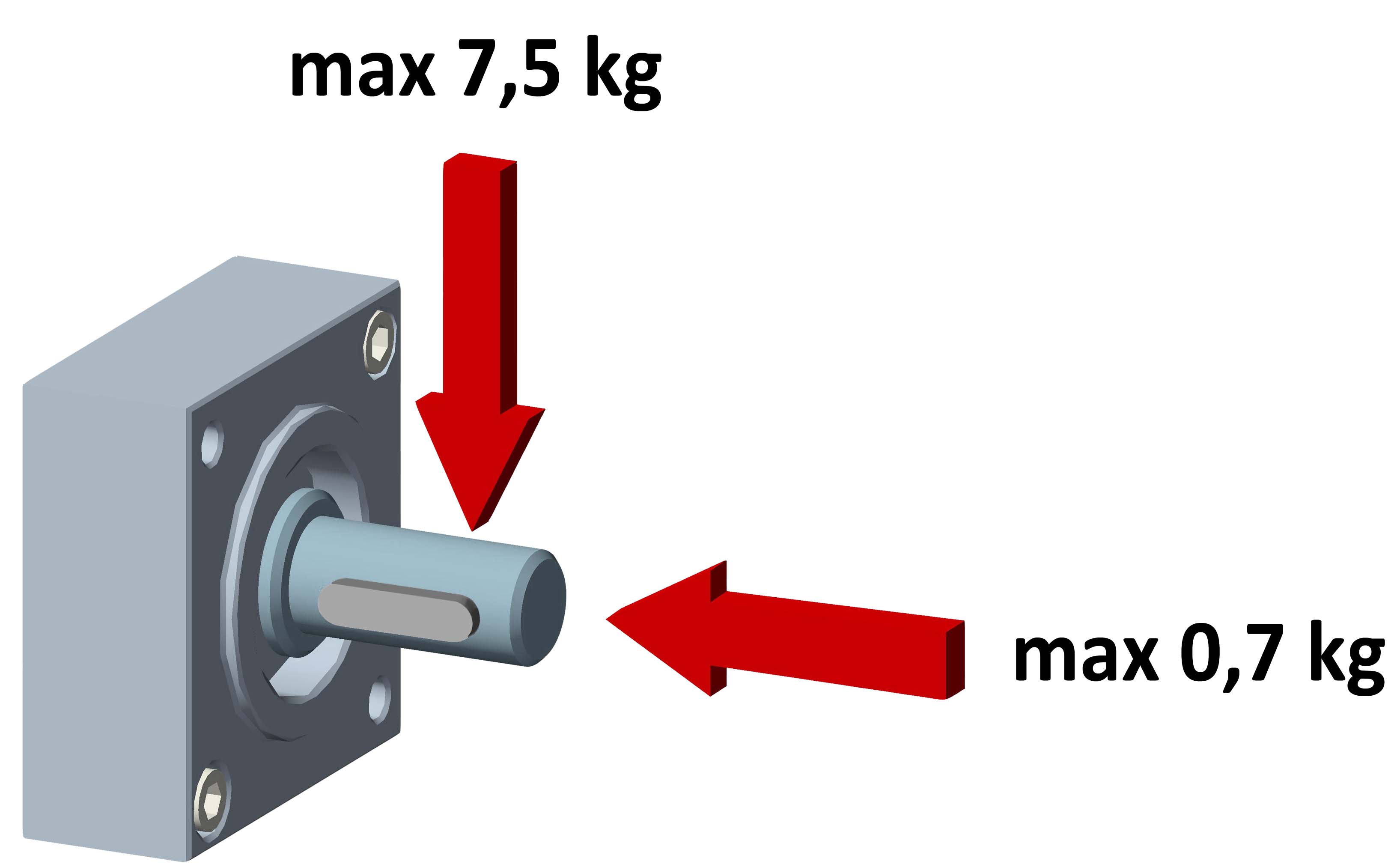
Fa = axial load
is the load acting of the shaft/axis
GEARBOX LIFETIME CALCULATION
THEORETIC EXPECTED LIFE* = 10.000H X FU
RECOMMENDED TORQUE (NM)
FU = ----------------------------------
APPLIED TORQUE (NM)**
* The lifetime of 10.000h considers the following conditions:
- Applied torque = advised torque (see tables)
- Maximum of 8 working hours per day
- Working temperature 20 ° - No shocks
** Output torque actually applied
*** Max torque applied
"To identify the most suitable gearbox for your requirements, refer to the values in the table. If the loads and efficiency are very close to the table values, contact the technical department".
Output torque with ratio 1:1
![]() Max torque
Max torque![]() Recomended torque
Recomended torque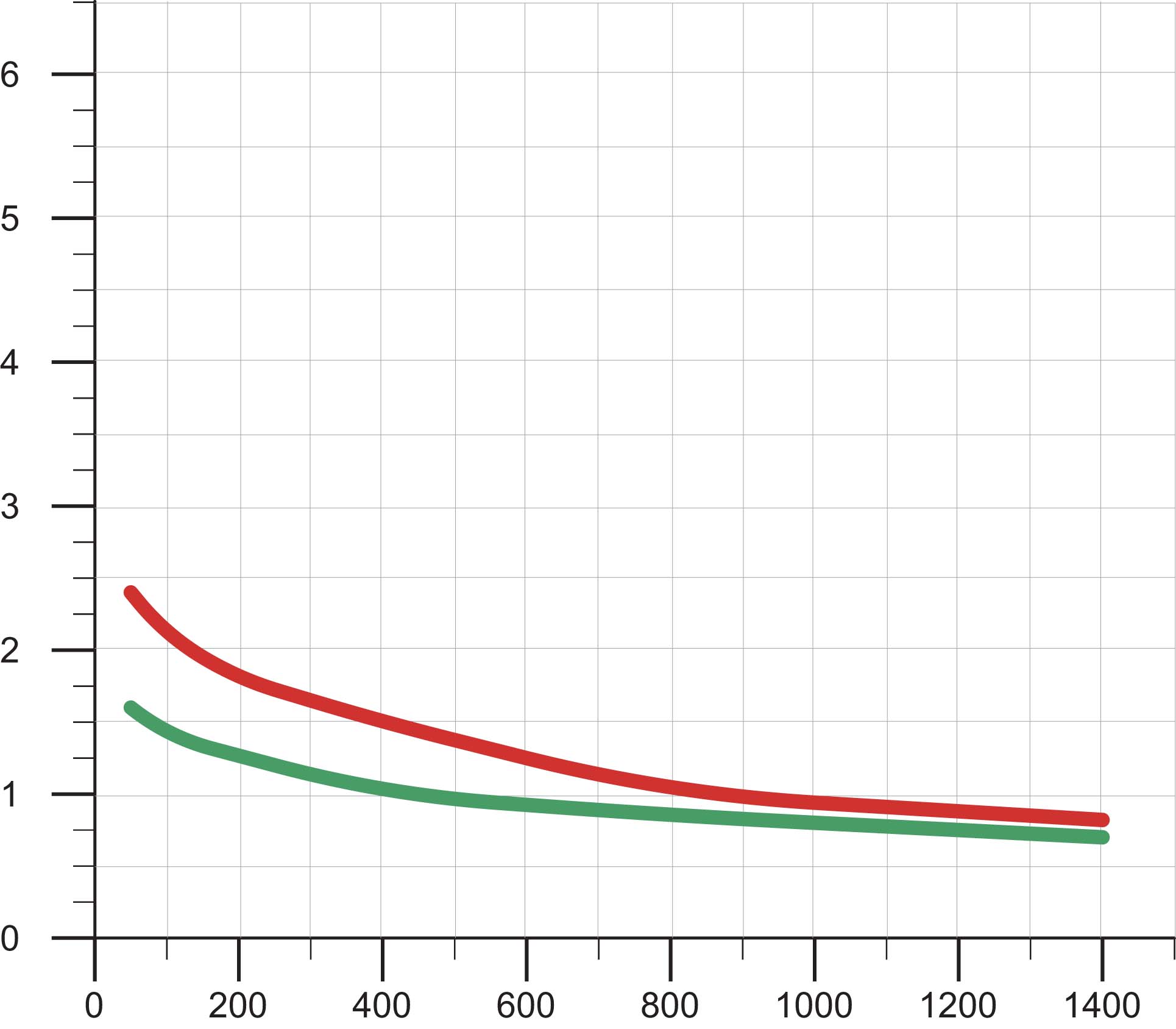
| Max Torque*** (Nm) | 3,8 | 3,3 | 2,7 | 2,4 | 2 | 1,6 |
| Recommended torque (Nm) | 2,5 | 2,2 | 1,8 | 1,6 | 1,3 | 1,1 |
| Rpm | 50 | 100 | 200 | 400 | 800 | 1400 |
Efficiency = 90°

