
TR
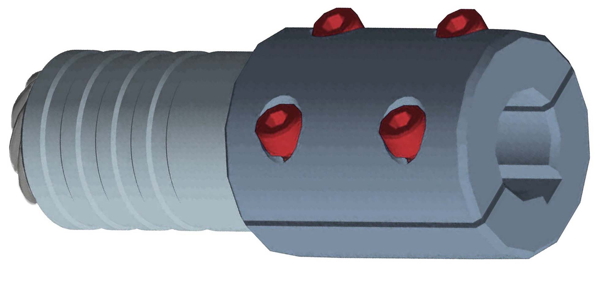
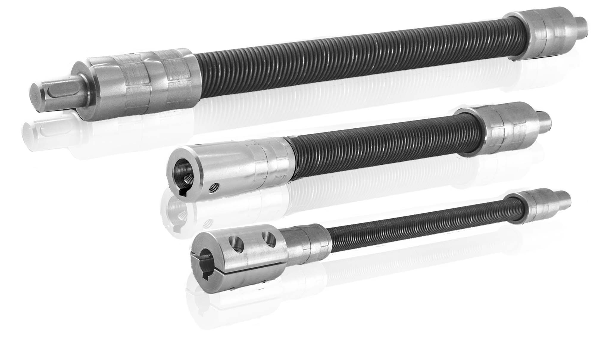
Flexible shafts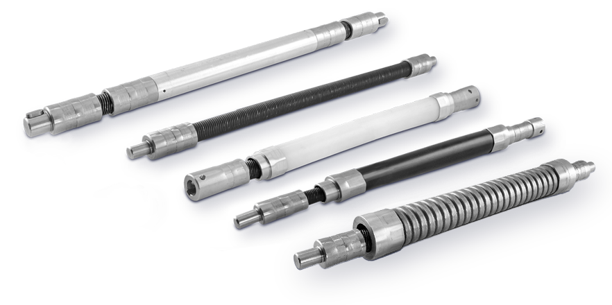
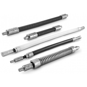
TR flexible shafts are highly versatile models that can be supplied also with different types of protective covers based on the type of application:
- transfer torque where a direct connection is not possible
- substitution of unprotected
- complex, or dangerous mechanisms
- remote operation of mechanisms
- reduce the overall weight of mechanisms
- bypass obstacles below, above, or around
| Version «A» = without protective cover |
 |
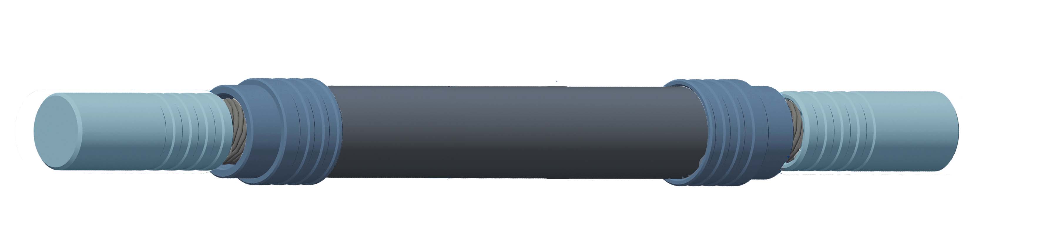
| Version «B» = with “Rilsan” protective cover |
|
|
|
recommended for protection against oil, grease, dirt, corrosive agents, nearby elements of the machine, etc. |
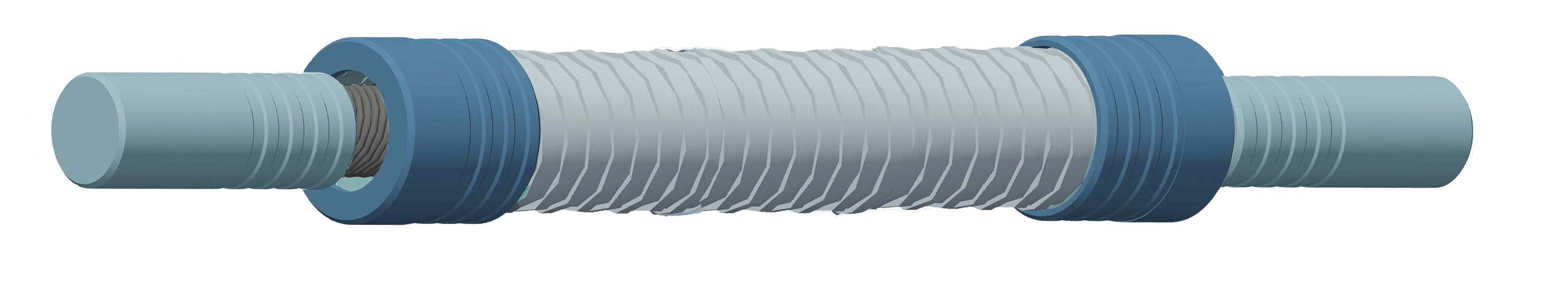
| Version «C» = with galvanized steel reinforced cover |
 |
|
recommended to increase mechanical robustness in particularly heavy working conditions. |
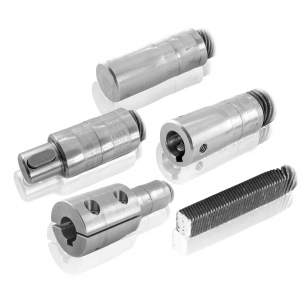
• Terminals made of stainless steel AISI 303, available models (☛see section "Accessories"):
| - cylindrical solid CL | - cylindrical female CF | - square Q |
 |
| - cylindrical male CM | - cylindrical male/bushing CMB |
|
|
 |

Photogallery
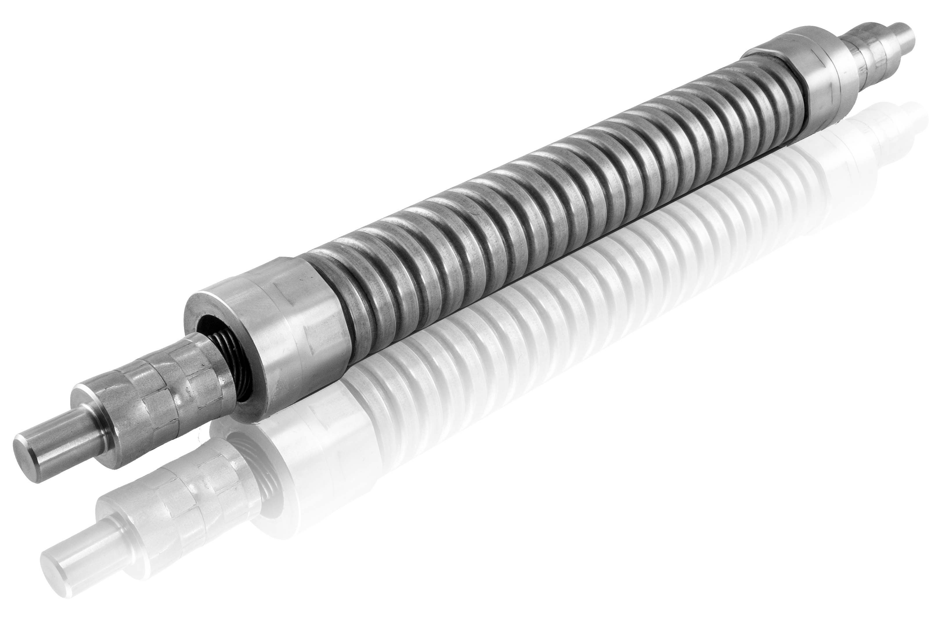
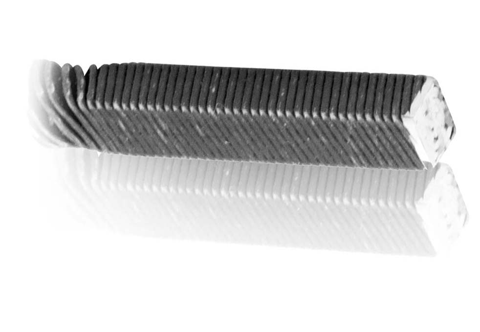
| Model < TR-A > without protective cover |
| DIMENSION TABLE | |
| VERSION | FLEXIBLE SHAFT |
| Ø A | |
| TR6A | 6 |
| TR8A | 8 |
| TR10A | 10 |
| TR12A | 12 |
| TR15A | 15 |
| TR20A | 20 |
| The data refers to length L=1000mm |

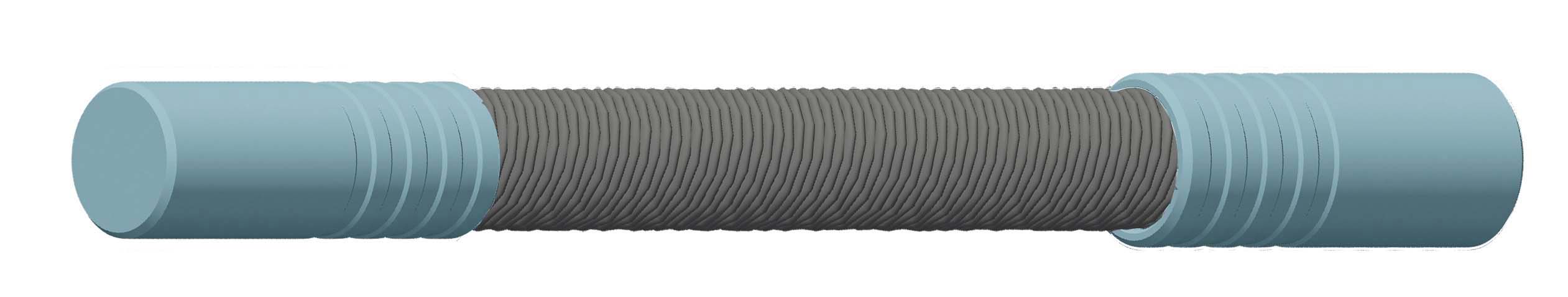
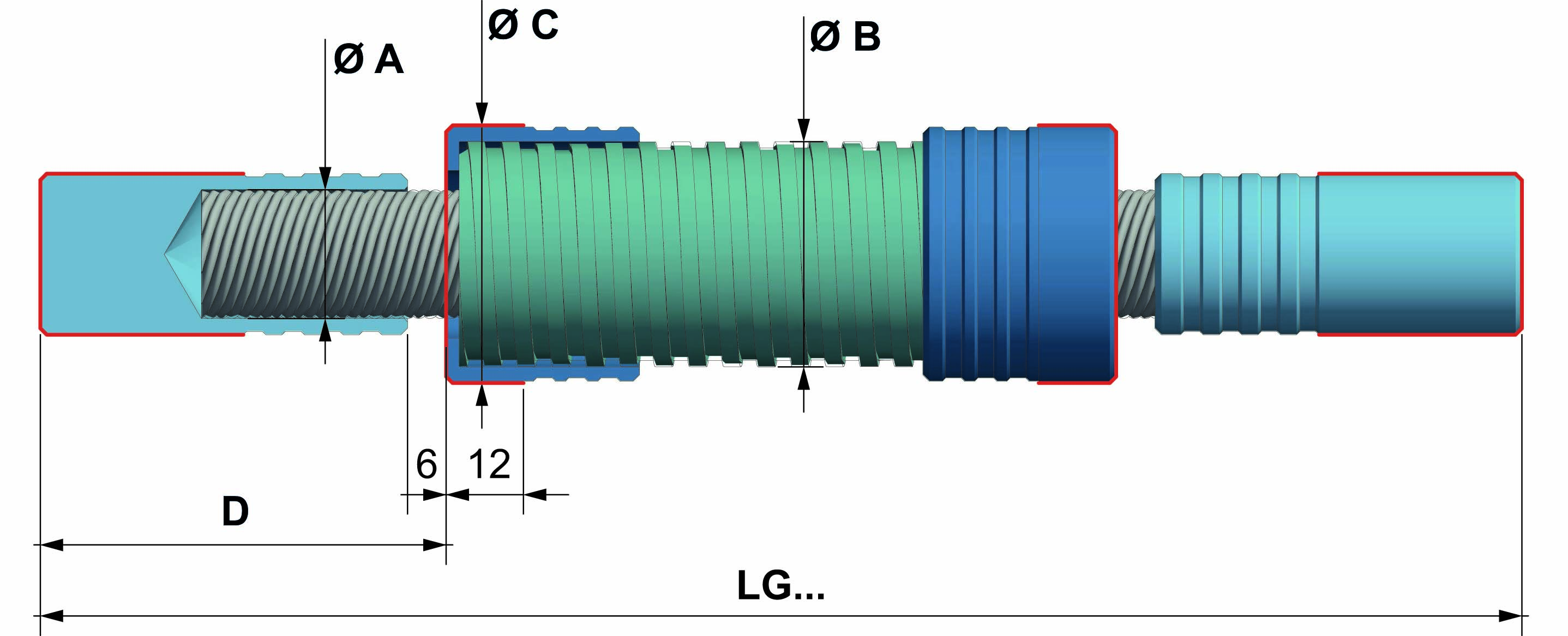
| Model < TR-B > with protective cover made of "Rilsan" |

Black “Rilsan” plastic for ø6-8-10-12-15 mm sizes;
White "Rilsan” for a ø20 size.
| DIMENSION TABLE | ||||
| VERSION | FLEXIBLE SHAFT | EXTERNAL COVER | TERMINAL COVER | LENGTH + 6mm* |
| Ø A | Ø B | Ø C | D | |
| TR6B | 6 | 12 | 11 | 24 |
| TR8B | 8 | 14 | 13 | 44 |
| TR10B | 10 | 18 | 15 | 50 |
| TR12B | 12 | 20 | 18 | 64 |
| TR15B | 15 | 22 | 20 | 56 |
| TR20B | 20 | 30 | 28 | 63 |
| *Length + 6 (between terminal and cover terminal) |
| The data refers to length L=1000mm |

| Model < TR-C > with protective cover made of zinc-coated steel |
| DIMENSION TABLE | ||||
| VERSION | FLEXIBLE SHAFT | EXTERNAL COVER | TERMINAL COVER | LENGTH +6mm* |
| Ø A | Ø B | Ø C | D | |
| TR6C | 6 | 14 | 18 | 34 |
| TR8C | 8 | 17 | 21 | 44 |
| TR10C | 10 | 20 | 24 | 50 |
| TR12C | 12 | 25 | 30 | 54 |
| TR15C | 15 | 30 | 35 | 56 |
| TR20C | 20 | 35 | 40 | 63 |
| *Length + 6 (between terminal and cover terminal) |
| The data refers to length L=1000mm |


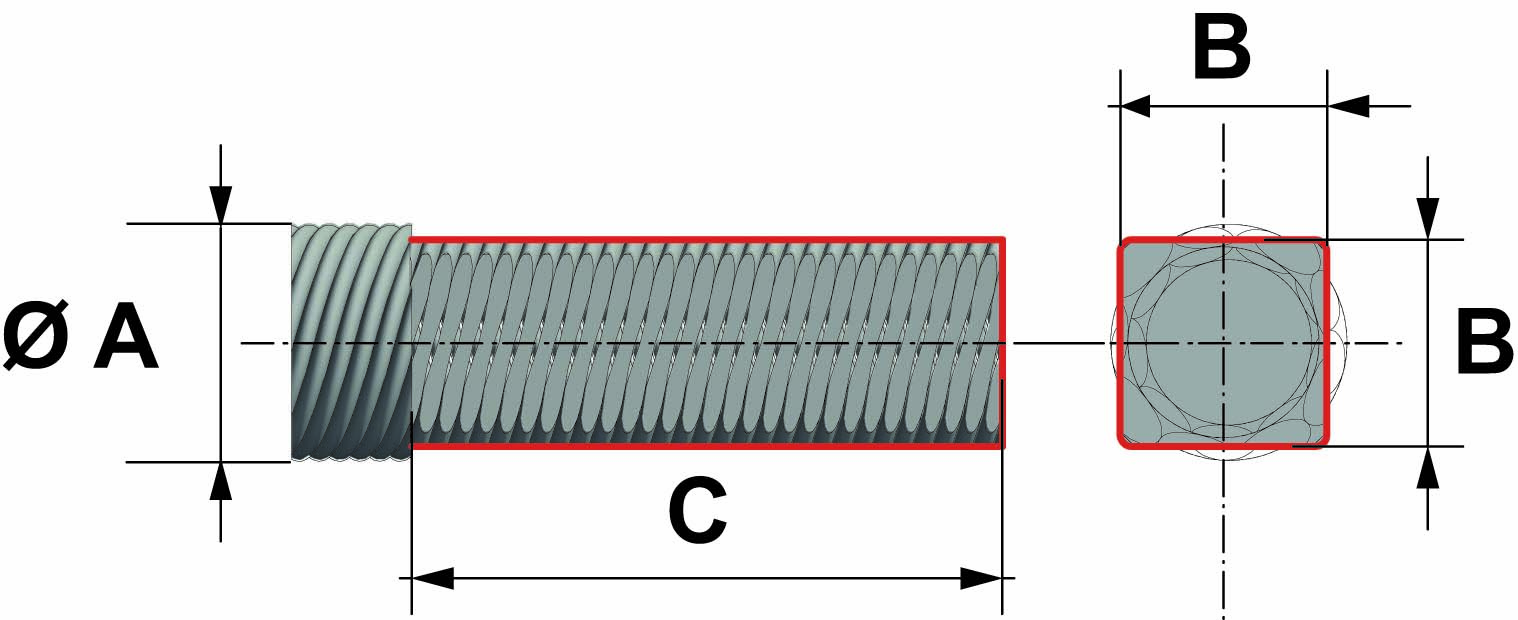
FIXING TERMINALS
made of stainless steel AISI 303, available models:
| Q = square |
 |
| |
|
 |
|
| FLEXIBLE SHAFT | EXTERNAL SQUARE | TOTAL LENGTH |
| Ø A | Ø B | C |
| 6 | 5 | 30 |
| 8 | 6.5 | 35 |
| 10 | 8.5 | 40 |
| 12 | 10 | 40 |
| 15 | 13 | 45 |
| 20 | 17.5 | 45 |
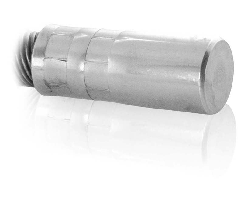
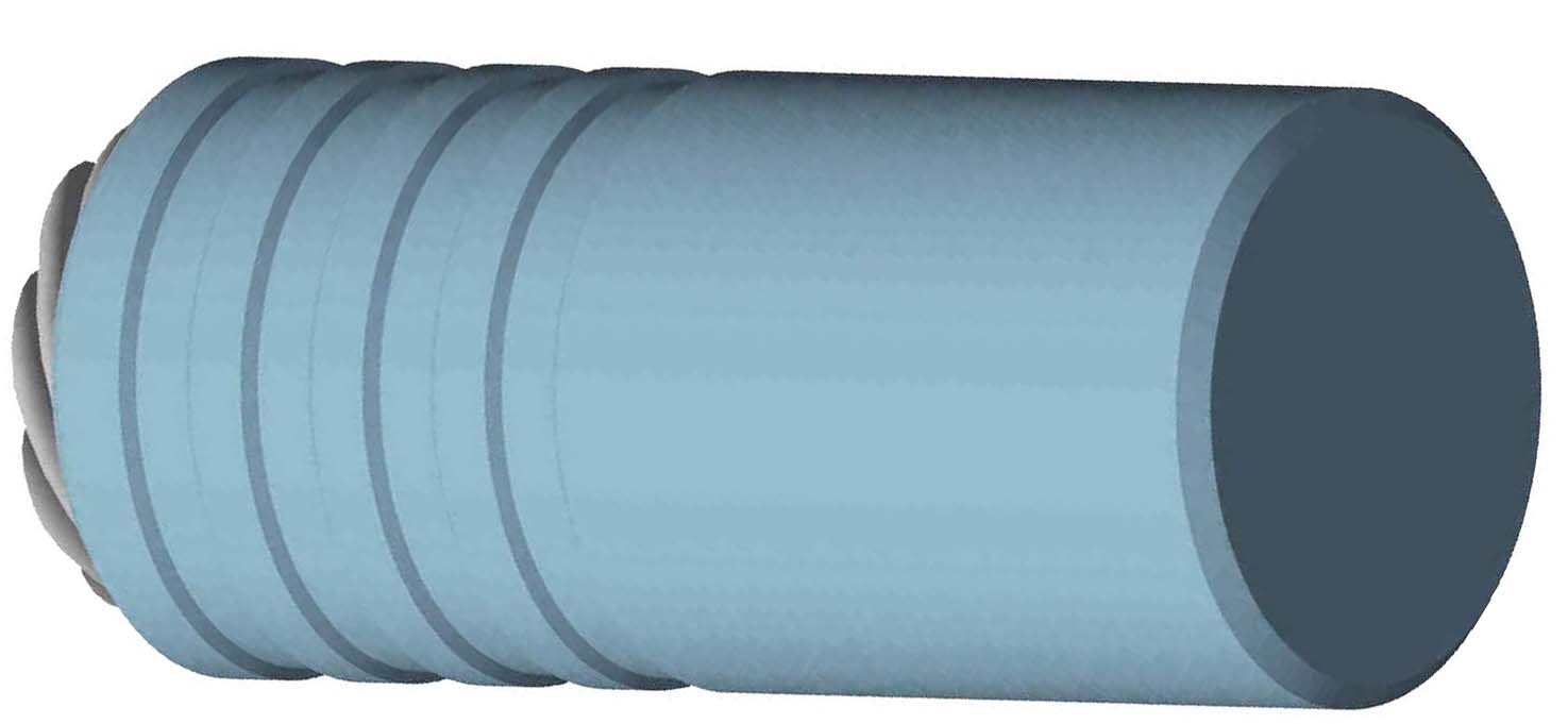
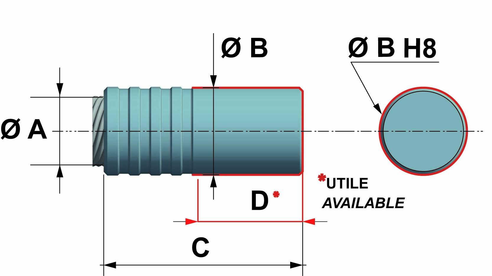
| CL = cylindrical solid |
 |
 |
|
 |
|
| FLEXIBLE SHAFT | EXTERNAL DIAMETER | TOTAL LENGTH | AVAILABLE LENGTH |
| Ø A | Ø B | C | D |
| 6 | 10 | 28 | 12 |
| 8 | 12 | 38 | 16 |
| 10 | 14 | 44 | 20 |
| 12 | 16 | 48 | 22 |
| 15 | 20 | 50 | 25 |
| 20 | 25 | 57 | 30 |
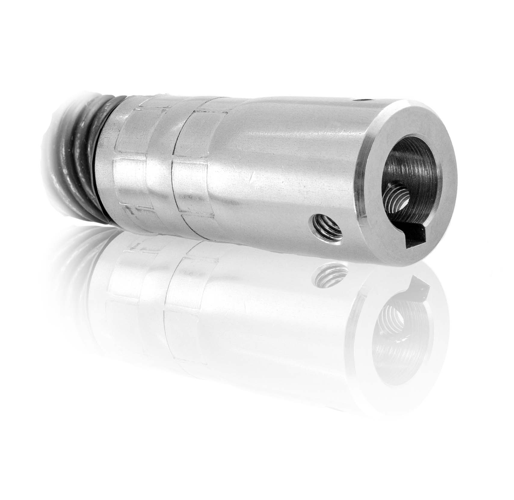
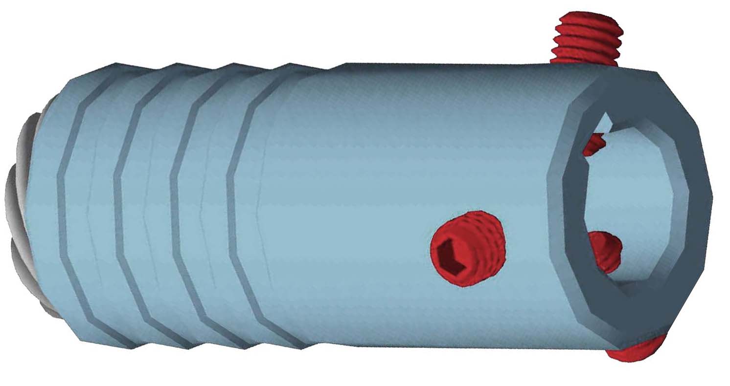
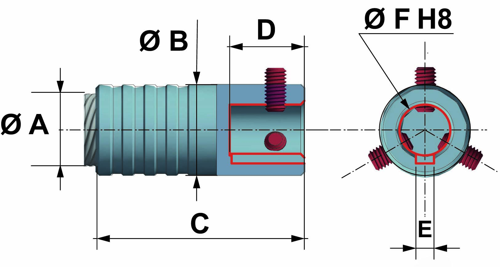
| CF = cylindrical female |
 |
 |
|
 |
|
| FLEXIBLE SHAFT | EXTERNAL DIAMETER | TOTAL LENGTH | BORE DEPTH | KEYWAY | BORE |
| Ø A | Ø B | C | D | E | Ø F |
| 6 | 12 | 28 | 10 | = | 6 |
| 8 | 16 | 38 | 15 | = | 8 |
| 10 | 16 | 44 | 15 | = | 8 |
| 12 | 20 | 48 | 16 | 3 | 10 |
| 15 | 20 | 50 | 16 | 3 | 10 |
| 20 | 25 | 57 | 20 | 5 | 14 |
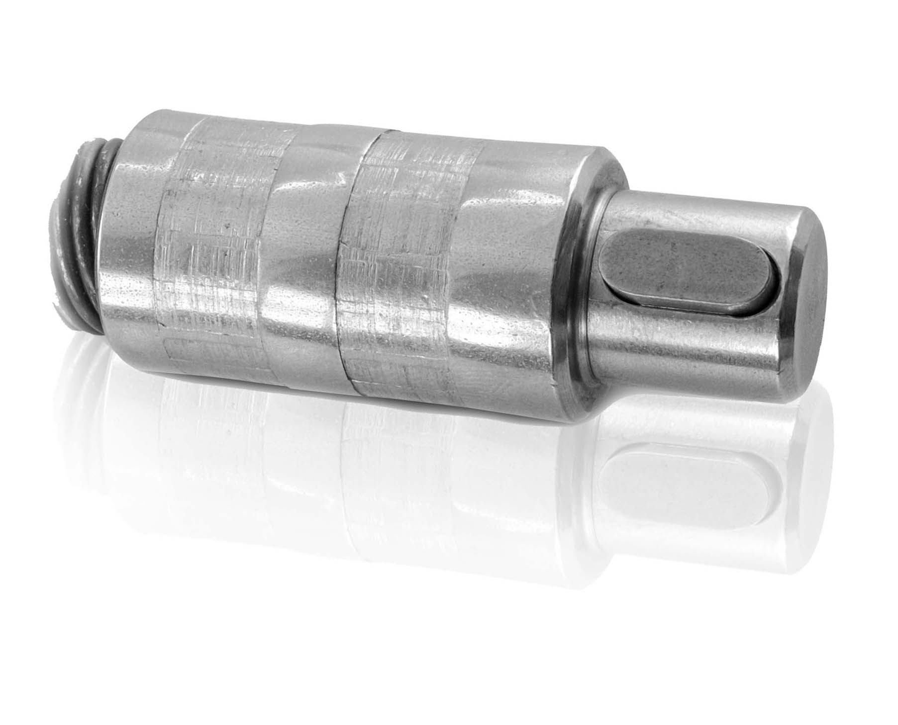
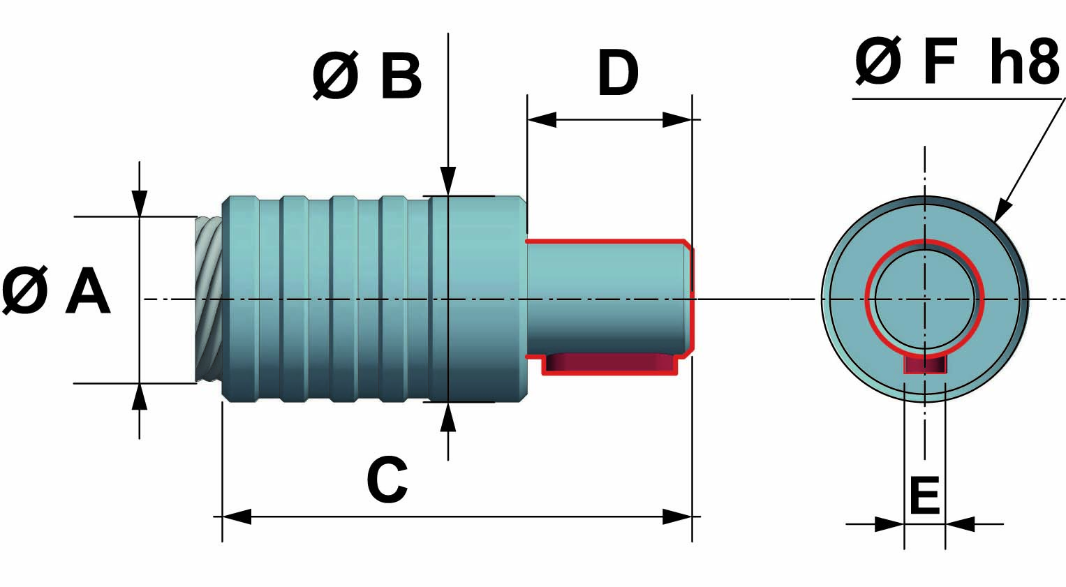
| CM = cylindrical male |
 |
 |
|
 |
|
| FLEXIBLE SHAFT | EXTERNAL DIAMETER | TOTAL LENGHT | AVAILABLE LENGTH | KEYWAY | MALE DIAMETER |
| Ø A | Ø B | C | D | E | Ø F |
| 6 | 10 | 28 | 10 | = | 6 |
| 8 | 12 | 38 | 14 | = | 8 |
| 10 | 14 | 44 | 14 | = | 8 |
| 12 | 16 | 48 | 15 | 3 | 10 |
| 15 | 20 | 50 | 15 | 3 | 10 |
| 15 | 20 | 50 | 15 | 5 | 14* |
| 20 | 25 | 57 | 20 | 5 | 14 |
* optional
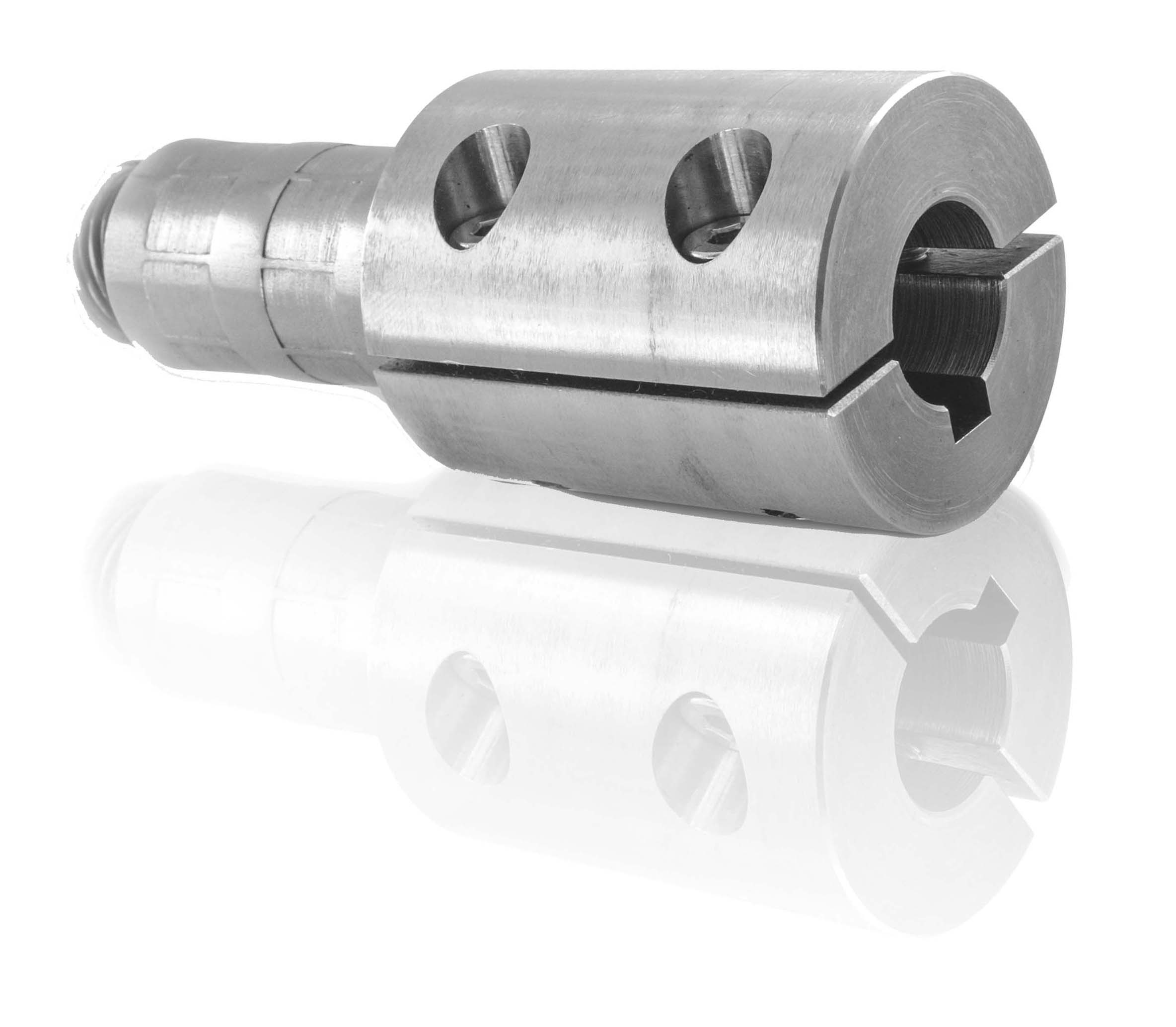
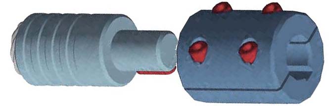
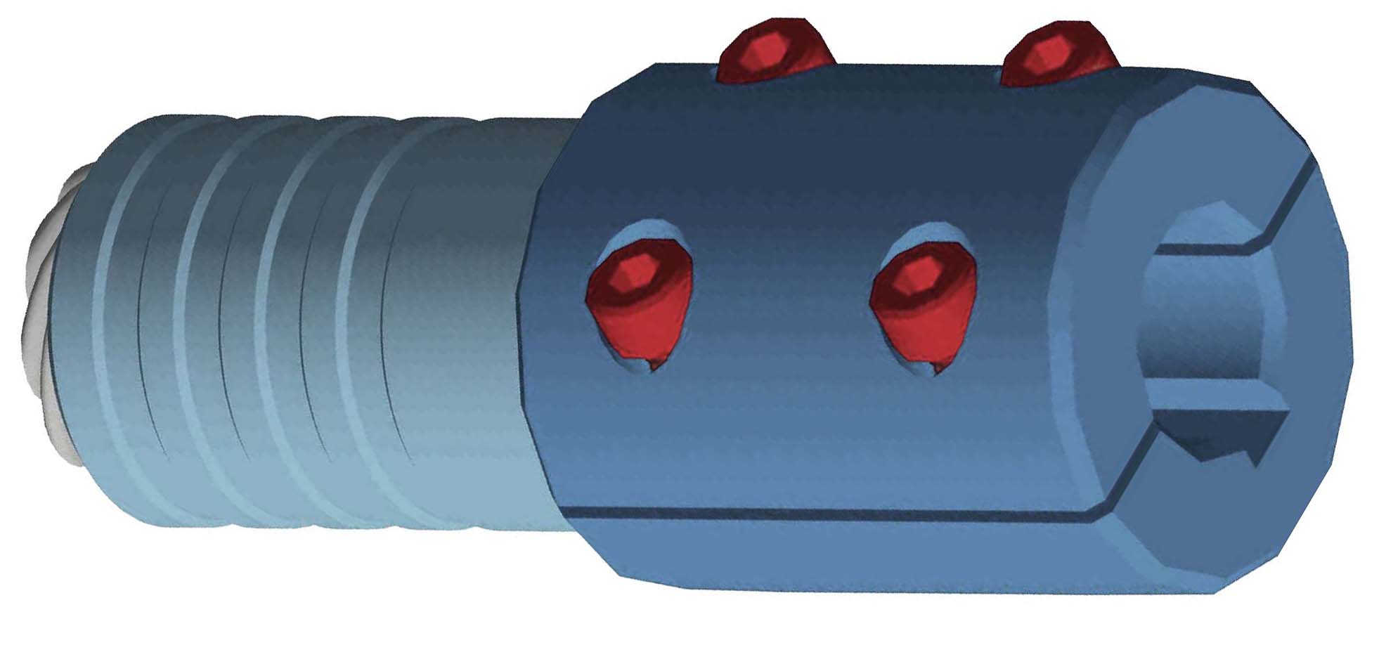
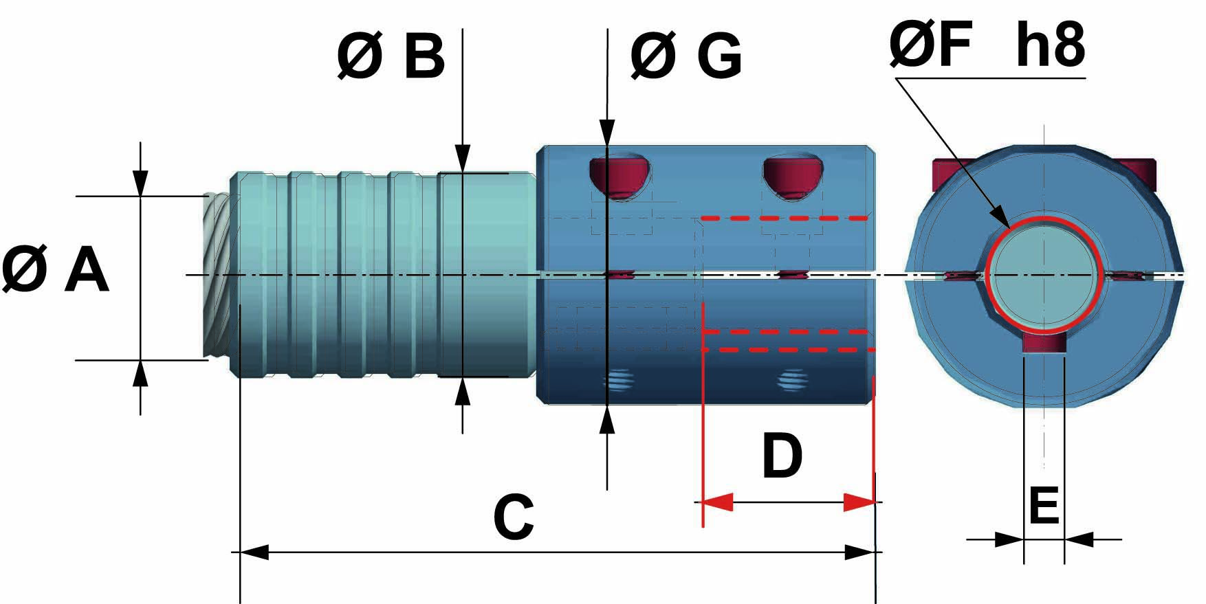
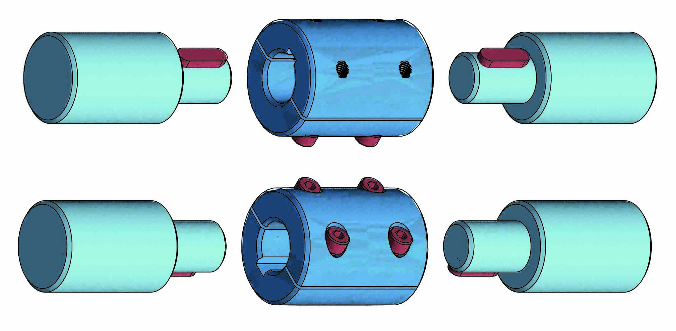
| CMB = 2 piece connection bushing |
 |
 |
|
 |
|
 |
|
| FLEXIBLE SHAFT | EXTERNAL DIAMETER | TOTAL LENGHT | AVAILABLE LENGTH | KEYWAY | BORE | EXTERNAL BUSHING |
| Ø A | Ø B | C | D | E | Ø F | Ø G |
| 6 | 10 | 28 | 10 | = | 6 | 14 |
| 8 | 12 | 38 | 14 | = | 8 | 22 |
| 10 | 14 | 44 | 14 | = | 8 | 22 |
| 12 | 16 | 48 | 15 | 3 | 10 | 24 |
| 15 | 20 | 50 | 15 | 3 | 10 | 24 |
| 15 | 20 | 50 | 15 | 5 | 14* | 32* |
| 20 | 25 | 57 | 20 | 5 | 14 | 32 |
* optional

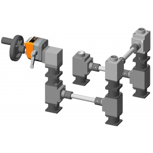
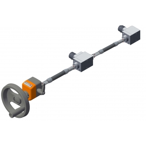
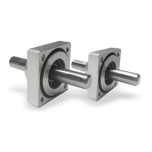
COUPLING BUSHES 2 piece bushing to couple gearboxes and shafts.
Available bores Ø: 6 - 8 -10 -14.
➜ for more complete information, see BT
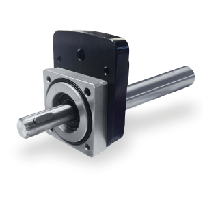
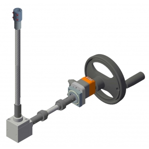
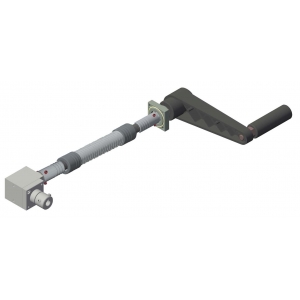
Flanged supports with extension shaft for coupling with position indicators.
➜ for more complete information, see Flanged supports
Richiedi l'accesso
| EFFICIENCY TABLE <TR> version A - B - C | ||||||
| FLEXIBLE SHAFT | TORSION | MIN. BENDING RADIUS | TORQUE | WEIGHT <TR-A> | WEIGHT <TR-B> | WEIGHT <TR-C> |
| Ø A | (°) | mm | Nm | gr | gr | gr |
| 6 | 80 | 70 | 3 | 400 | 600 | 800 |
| 8 | 70 | 90 | 4.5 | 600 | 800 | 1150 |
| 10 | 70 | 130 | 7.5 | 800 | 1000 | 1450 |
| 12 | 50 | 160 | 9 | 950 | 1350 | 1800 |
| 15 | 28 | 300 | 12 | 1200 | 1750 | 2200 |
| 20 | 18 | 400 | 18.5 | 1700 | 2150 | 3600 |
| The data refers to length L=1000mm |
|
MECHANICAL CHARACTERIZATION OF FLEXIBLE SHAFTS |
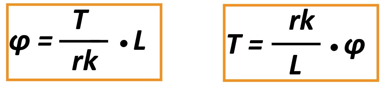
Flexible shafts are mechanical elements which are subject to torque and undergo a rotational elastic deformation. Considering a single flexible shaft, the equal and opposite torques which are applied at each extremity cause a relative rotation of the various sections which is proportional to the distance between the sections. The relation between Applied Torque T [Nm] and Twist Angle of the extremities φ [°] is a function of three parameters as follows:
● Torsional Rigidity k [103Nm/°] which depends on the section diameter and its construction characteristics
● Length of the shaft L [mm]
● Rotation Direction r (dimensionless parameter which characterizes the asymmetric behavior of the shaft)
Parameter r is equal to 1 when the shaft is loaded according to the winding direction of the spiral; when loaded in the opposite direction, r < 1 as indicated in the following table:
| PARAMETERS OF FLEXIBLE SHAFT | ||||
| Diameter Ø |
k |
r |
Tmax |
Tmax [Nm] φ [°] (L=1000mm, Tmax) |
| 4 | 17 | 0.55 | 1.1 | 64.71 |
| 5 | 26 | 0.55 | 1.8 |
69.23 |
| 6 | 38 | 0.55 | 3.0 | 78.95 |
| 8 | 67 | 0.55 | 4.5 | 67.16 |
| 10 | 101 | 0.55 | 7.5 | 74.26 |
| 12 | 180 | 0.65 | 9.0 | 50.00 |
| 15 | 405 | 0.80 | 12.5 | 30.86 |
| 20 | 1050 | 0.85 | 18.5 | 17.62 |
| BENDING EFFICIENCY |
The above shows a qualitative-quantitative curve of the efficiency of the flexible shaft as a function of the bending radius.
For configurations which are almost in a straight line, the efficiency is equal to the maximum value 0.9.
The efficiency is nearly constant for high values of the bending radius and decreases rapidly down to 0.2 as the minimum bending radius is approached.
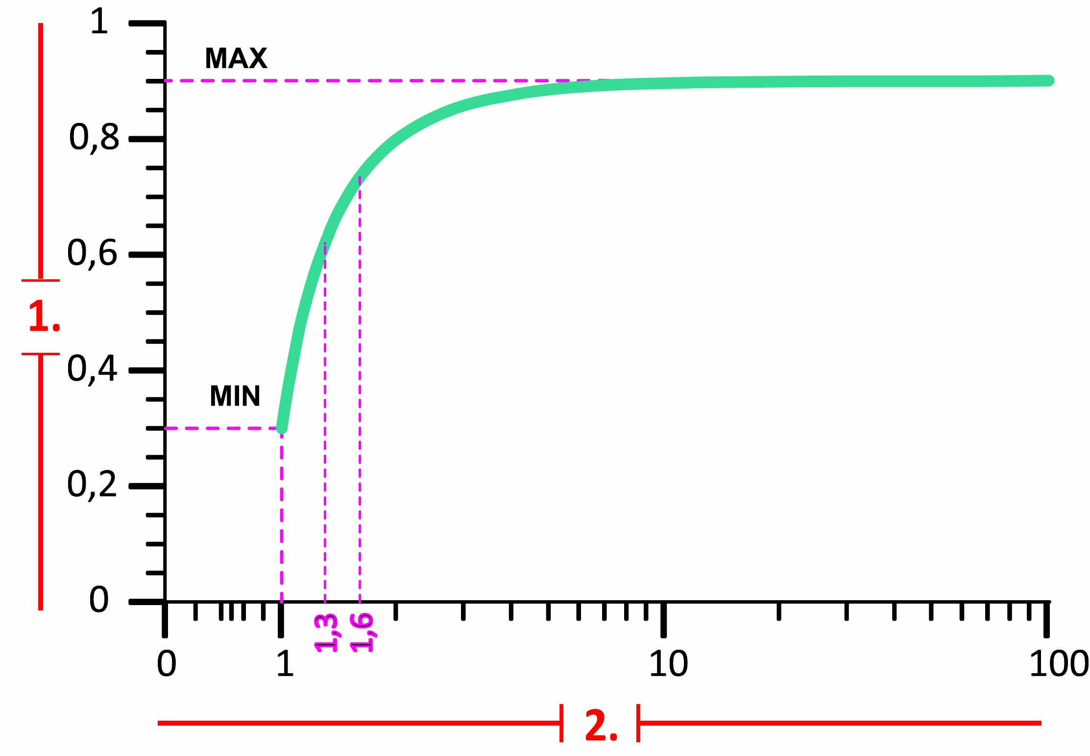
1. Efficiency
2. Bending radius/R min.
| DIAGRAM SHOWING TWIST ANGLE VS TORQUE FOR SHAFTS WITH A TOTAL LENGTH L=1000mm |
| FOR DIAMETERS FROM Ø4 TO Ø10 |
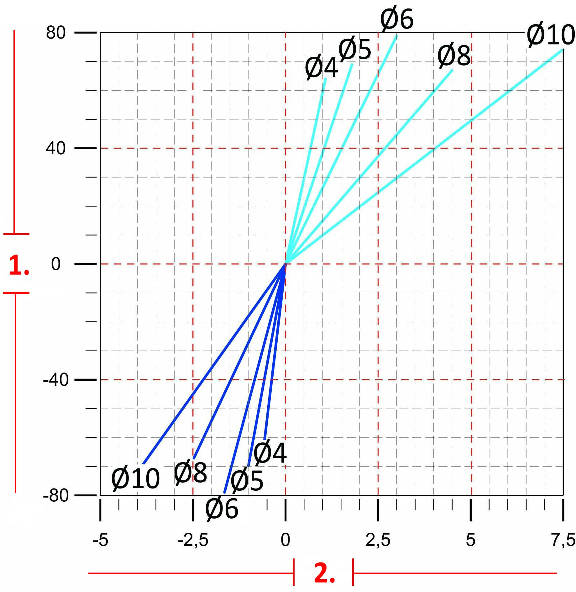
1. Twist angle φ [°]
2. Torque (Nm)
| FOR DIAMETERS FROM Ø12 TO Ø20 |
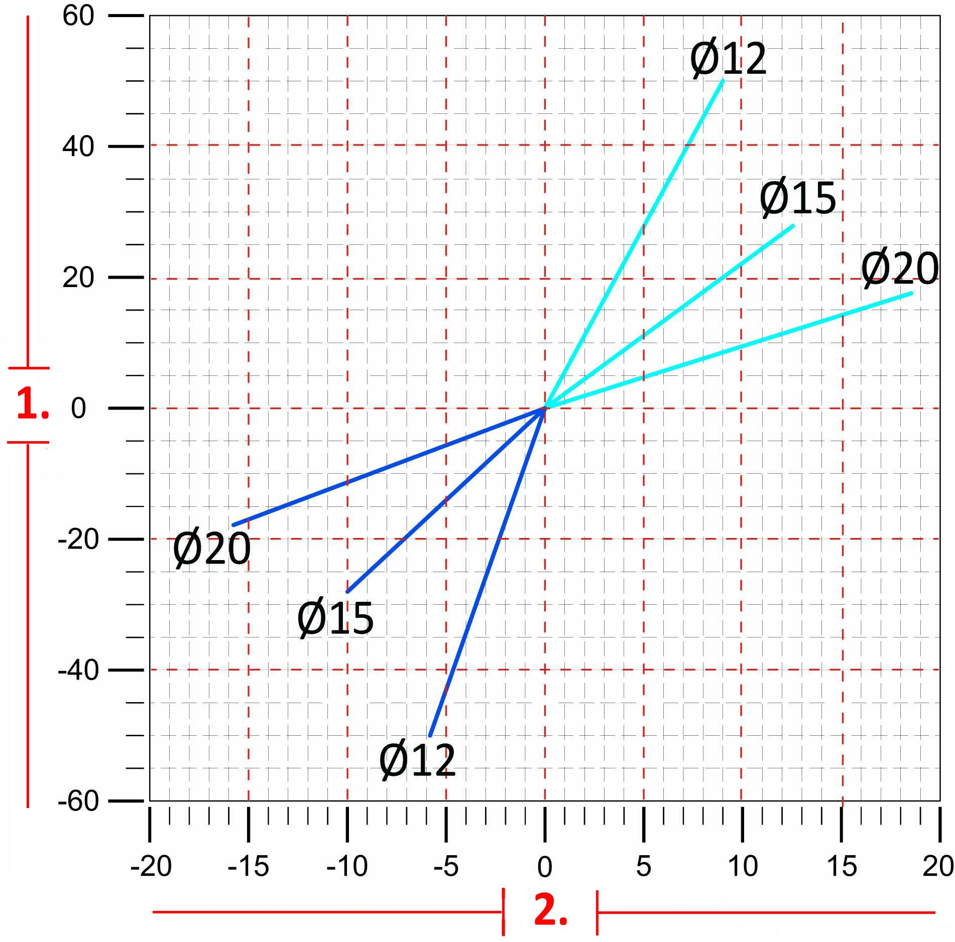
1. Twist angle φ [°]
2. Torque (Nm)
| GENERAL EFFICIENCY TABLE |
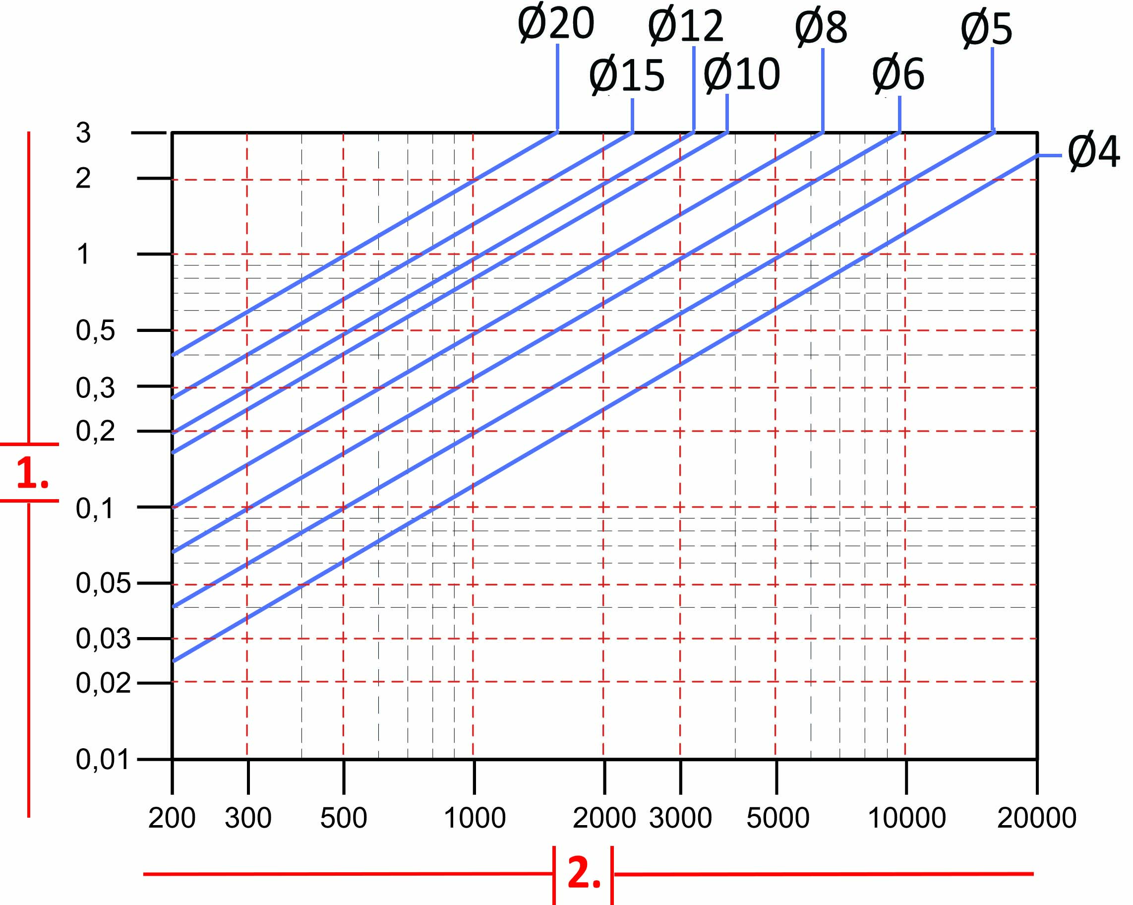
1. Power P (kw)
2. Rotation per minute (rpm)
| - To identify the most suitable flexible shaft for your requirements, refer to the values in the table. If the real loads and efficiency are very close to the table values, contact the technical department. |
| - To choose the most suitable flexibel shaft, we advise to consult the figures, tables, and the technical data shown in the “General Information” of this site. |
| - All tables show linear measurements expressed in <mm>, unless otherwise specified. All forces, efficiency and the loads are expressed in <N or Nm> (10 N ≅ 1 kg or 10Nm ≅ 1Kgm) unless otherwise specified. |


