
66/22
Gearboxes for intermittent use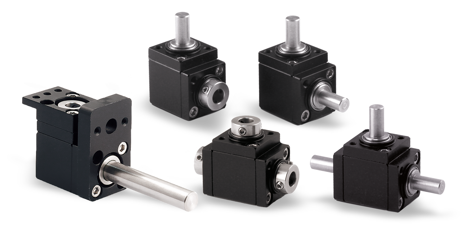
|
• Aluminium case, black anodised; stainless steel shafts. |
||
|
• Available with reduction ratio: 1:1. |
||
|
• Torque 2 Nm. Radial load 7,5 kg - axial load 0,7 kg. |
||
|
• Models: |
||
|
- Version «A» with 2 outputs; weight 50 g. |
||
|
- Version «B» with 3 outputs; weight 65 g. |
||
|
- Version «C» (opposite rotation) with 3 ouputs; weight 65 g. |
||
|
• Output shafts: <M> = male Ø6 / <F> = female Ø6. |
||
|
Available on request: |
|
|
|
▪ Output shafts: <F> = female Ø8 - Ø10 (only for version «A») |
||
|
▪Models with spiral bevel gears are available in all versions. |
||
|
▪ Grease fitting is available in all versions. |
||
|
▪ Machine-side coupling flange FL-M. |
||
|
▪ Male shaft flange for position indicators FL-OP/EP. |
Photogallery

|
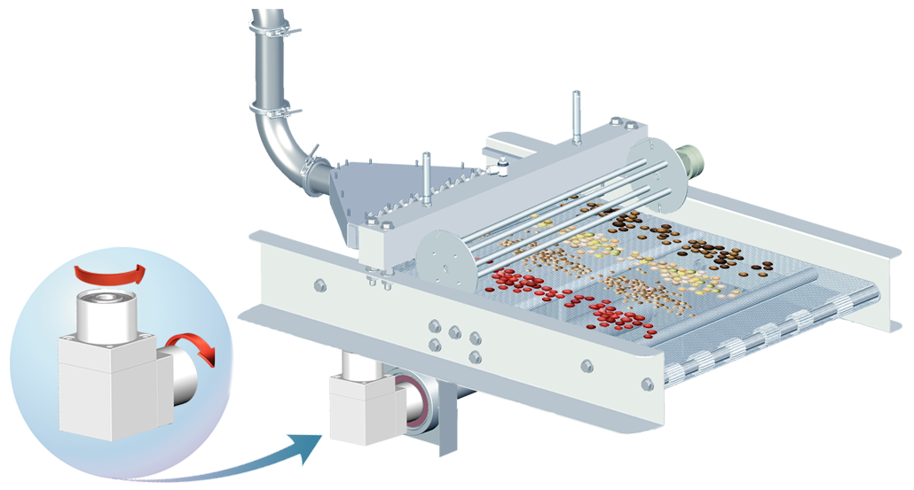
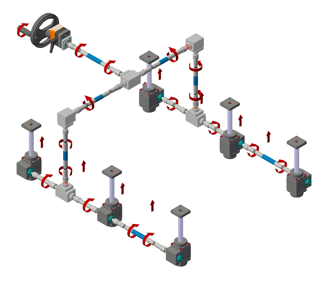
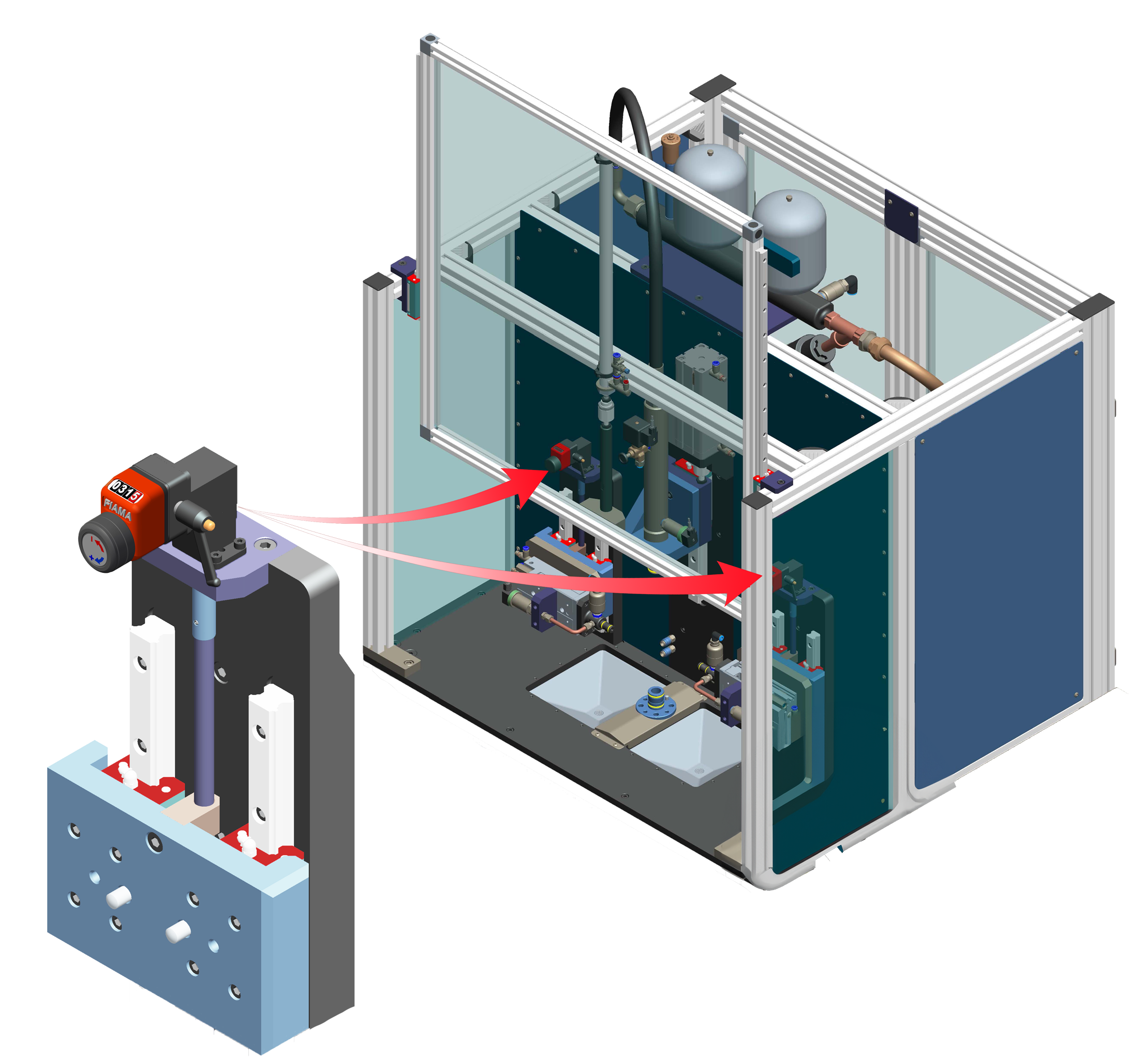
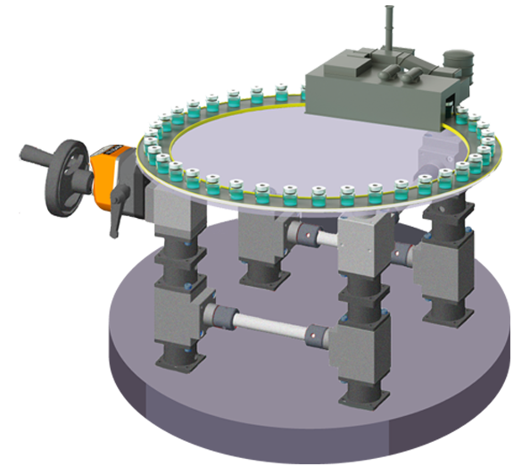
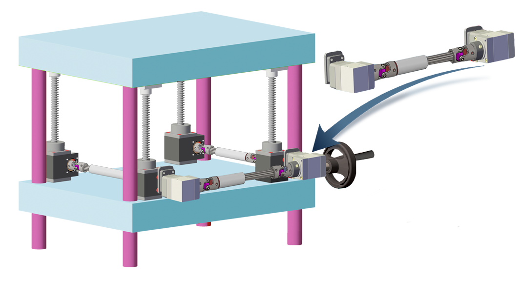
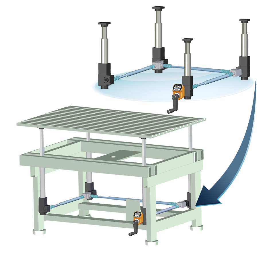
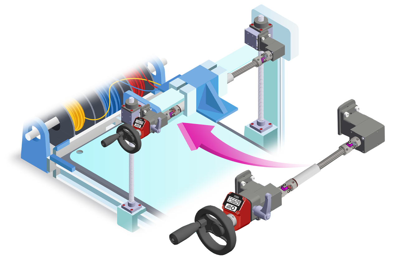
APPLICATION EXAMPLES |


| AVAILABLE SHAFTS | ||
| M = male Ø6 | F = female Ø6 | F = female ø8/ø10 |
 |
 |
 |
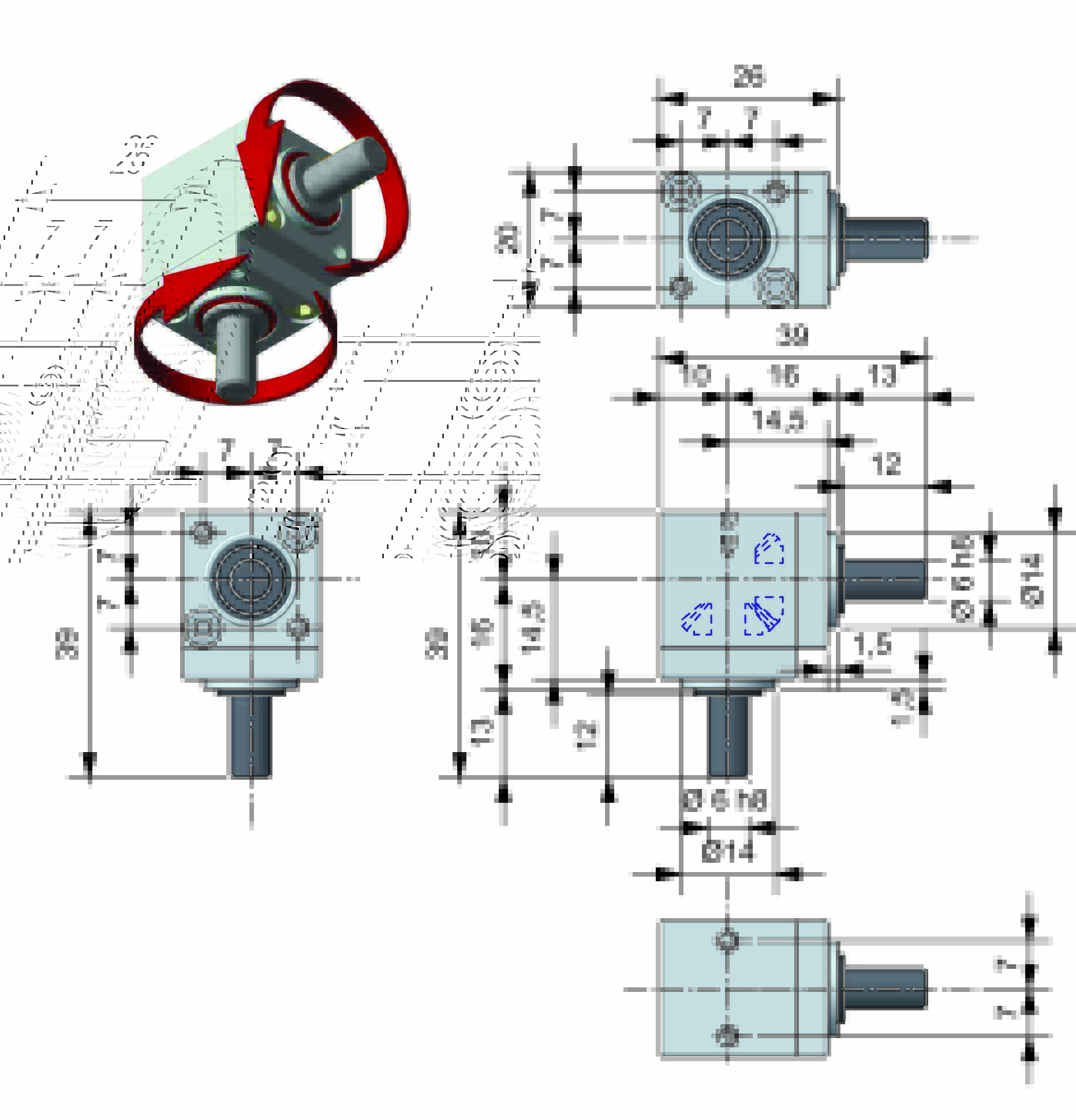
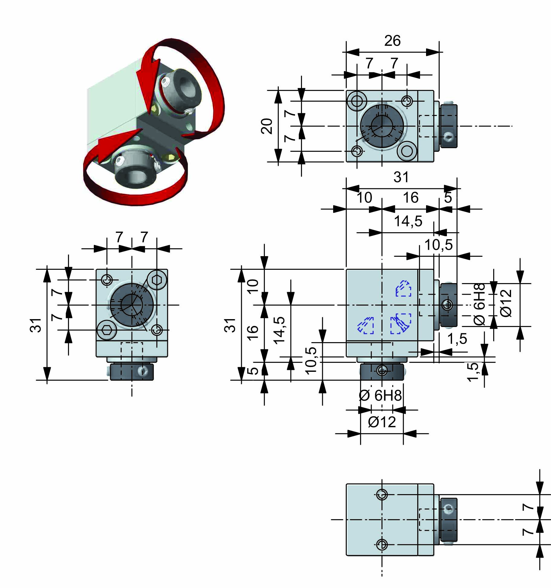
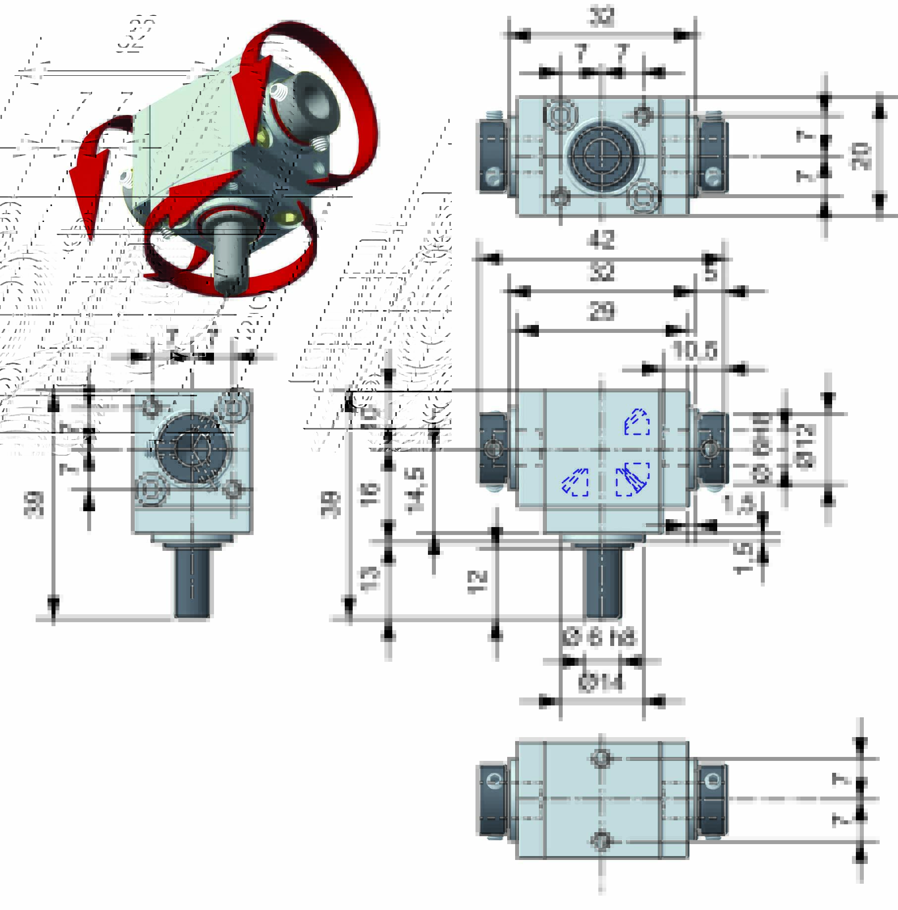
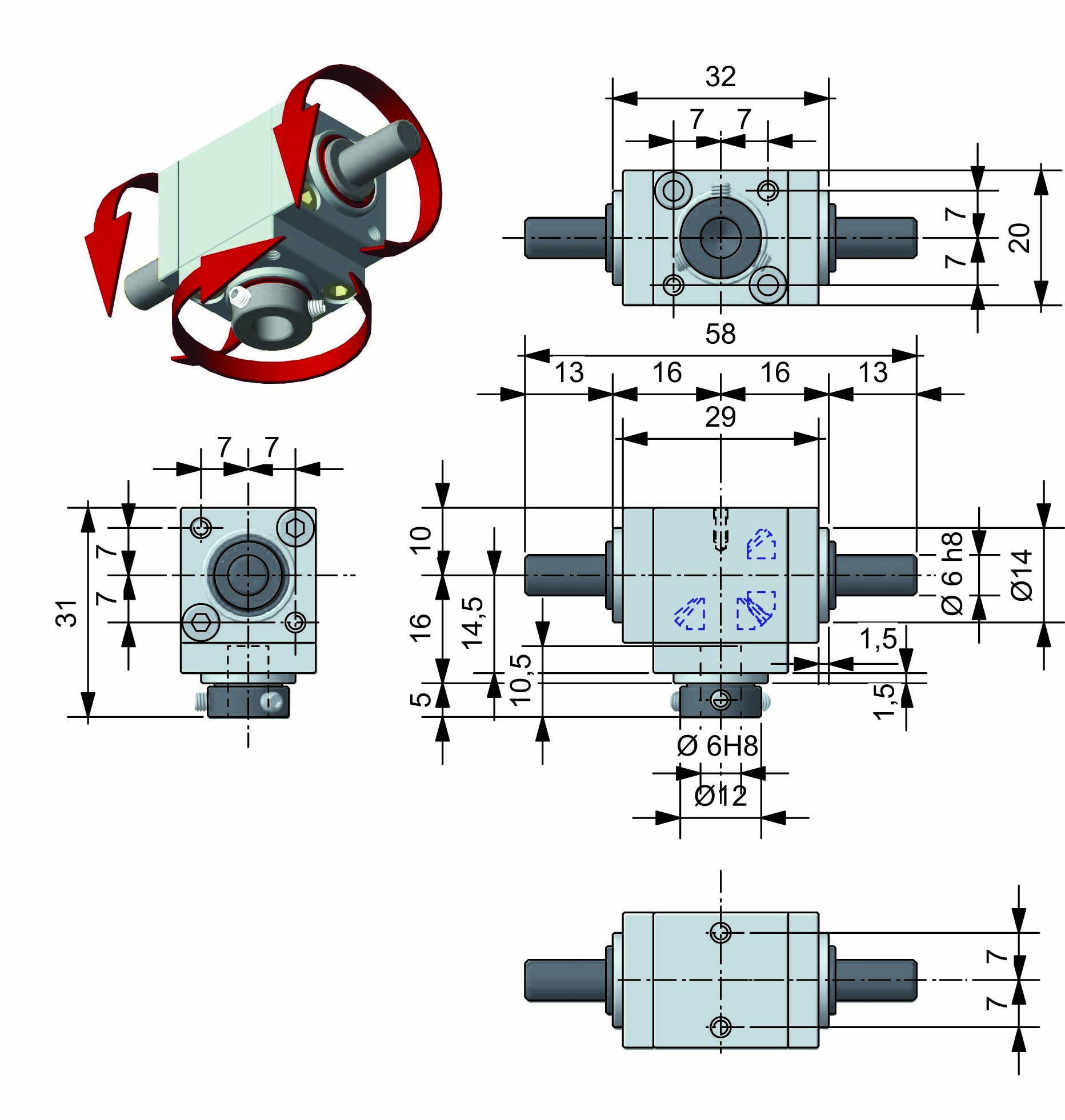
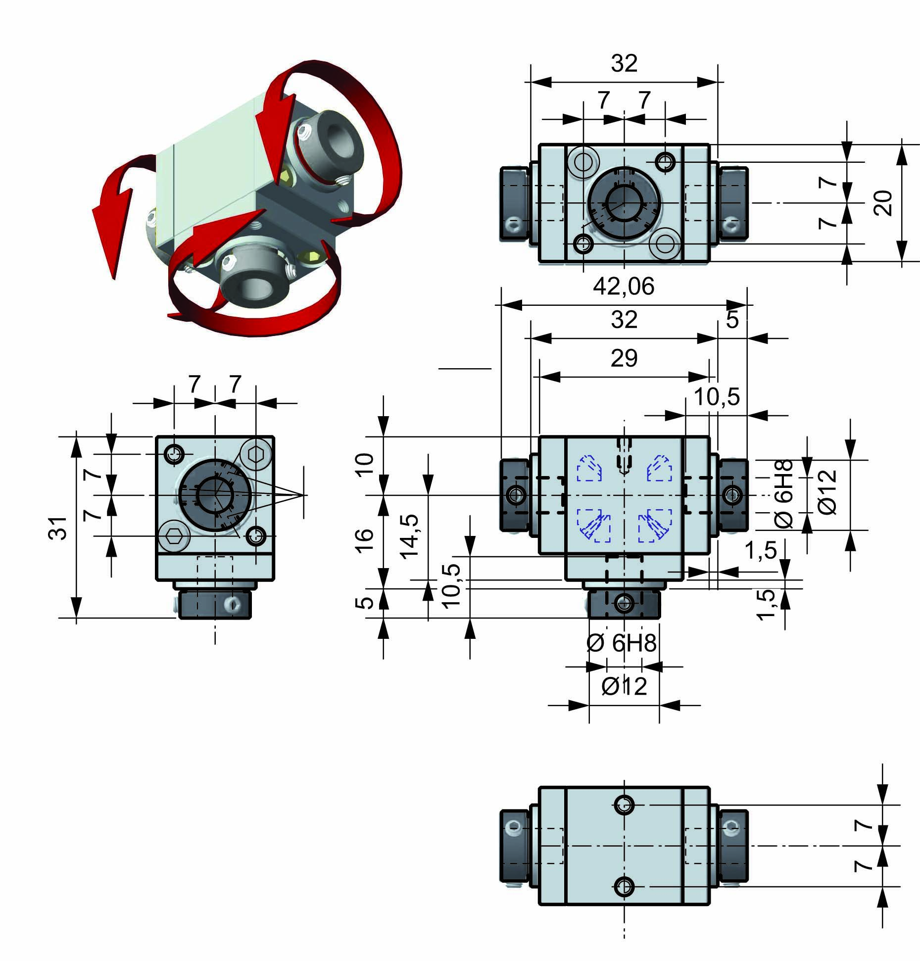
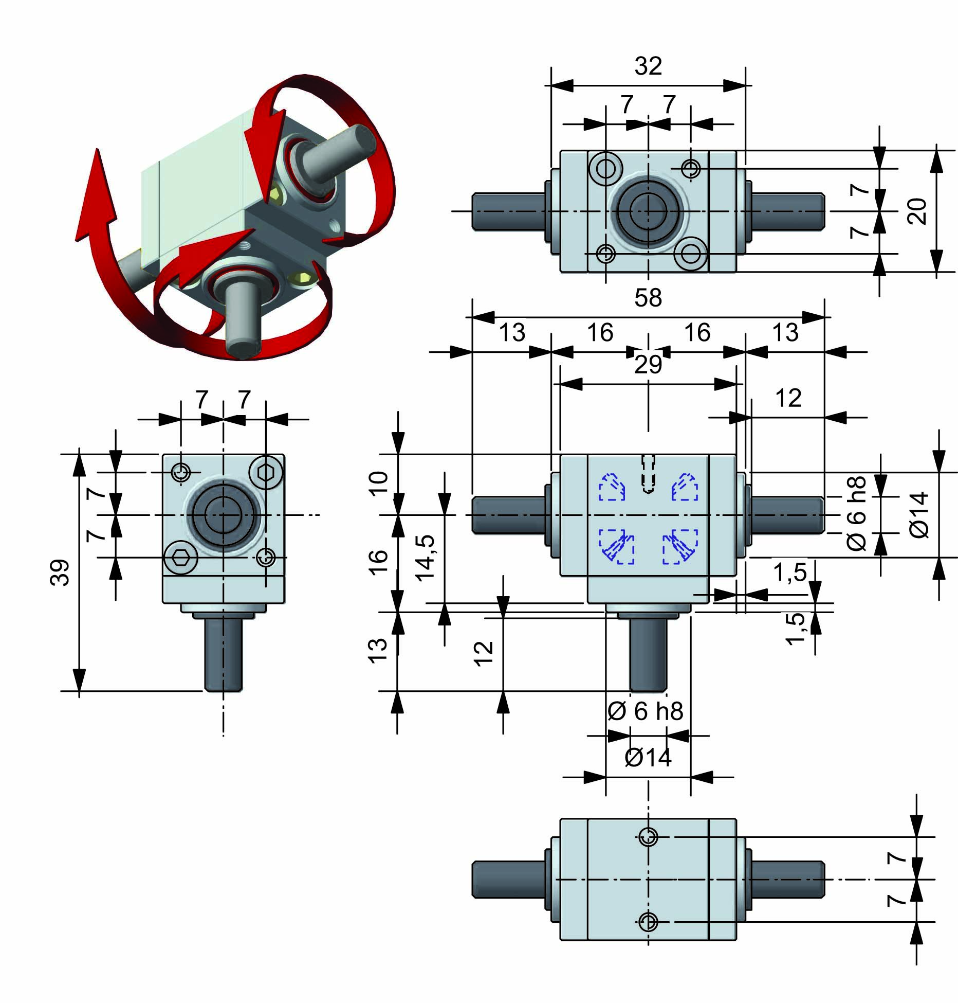
| DIMENSIONS |
| VERSIONS ⟪A⟫ - M-M |
 |
| VERSIONS ⟪A⟫ - M-F |
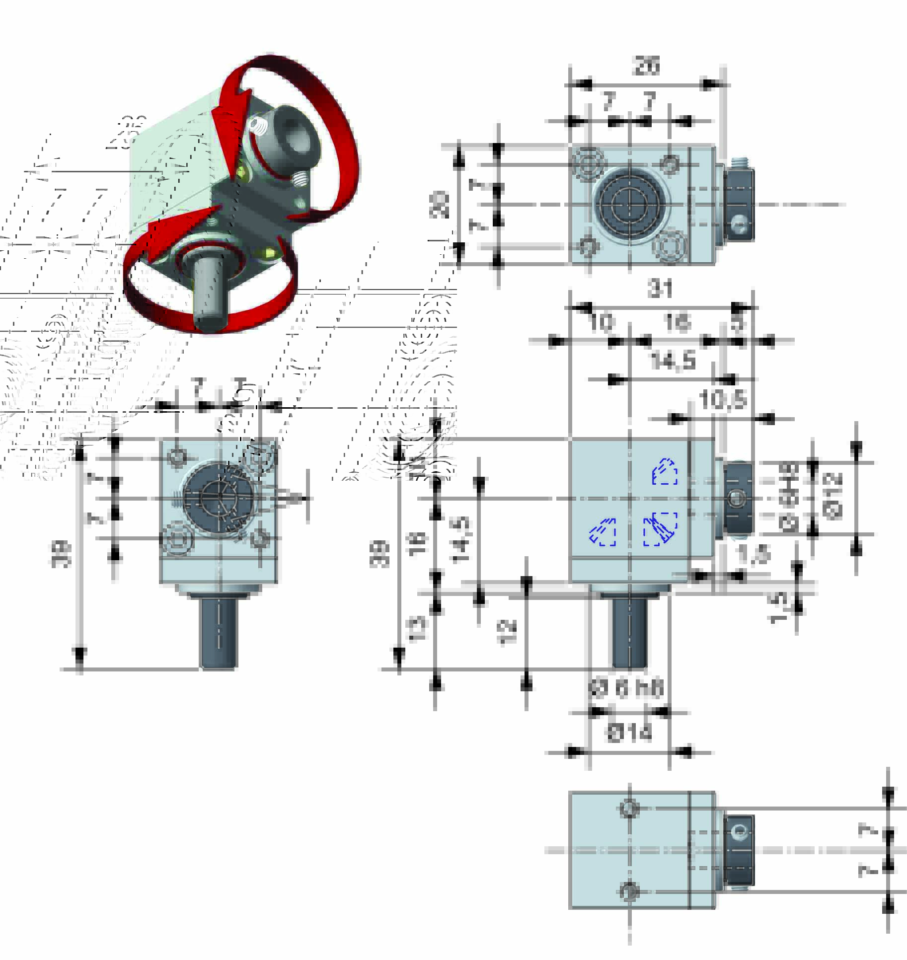 |
| VERSIONS ⟪A⟫ - F-M |
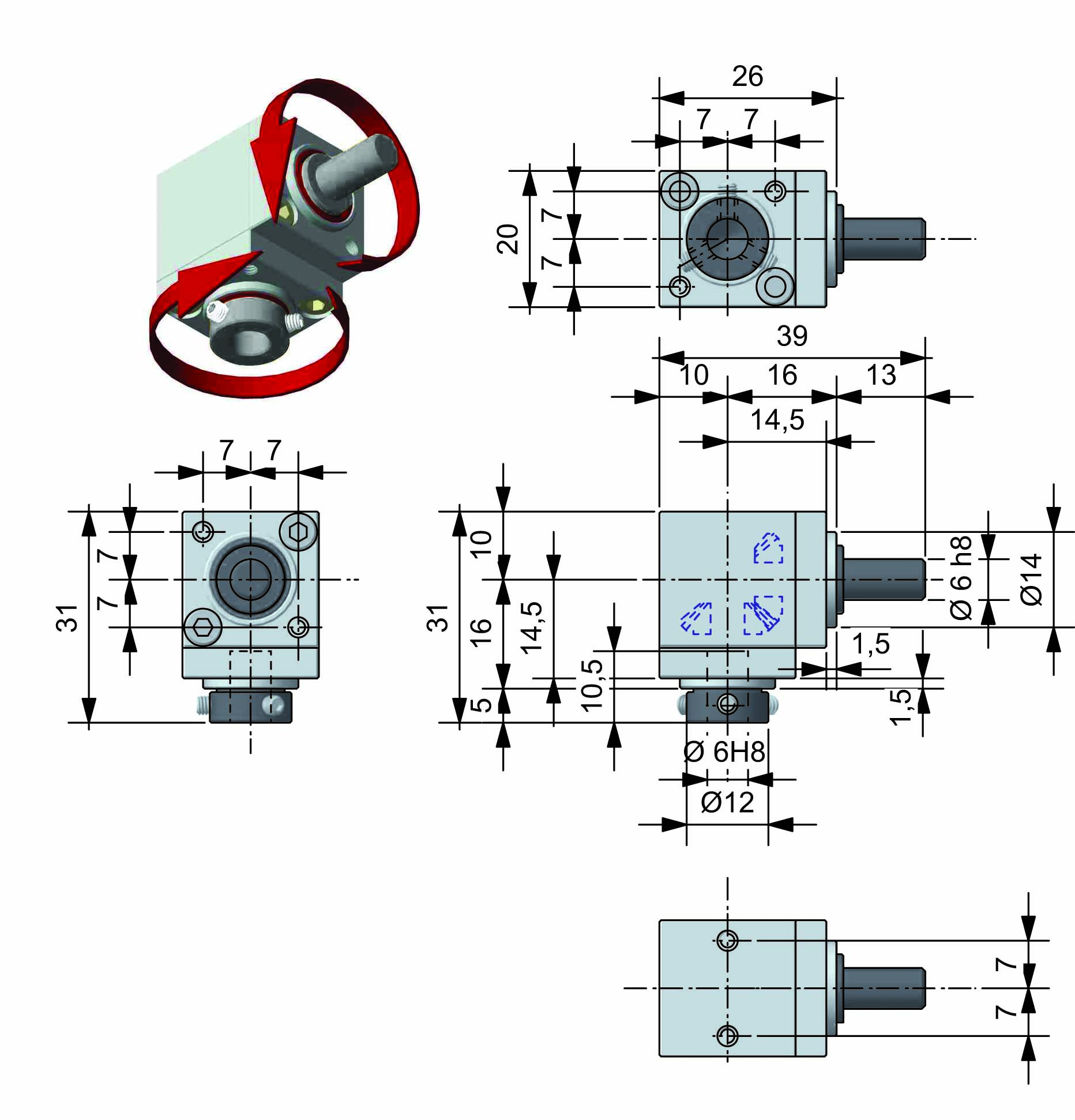 |
| VERSIONS ⟪A⟫ - F-F |
 |
| VERSIONS ⟪A⟫ - F(Ø8)-F(Ø8) |
F(Ø8).jpg) |
| VERSIONS ⟪A⟫ - F(Ø10)-F(Ø10) |
F(Ø10)_1.jpg) |
| VERSIONS ⟪B⟫ - M-M-M |
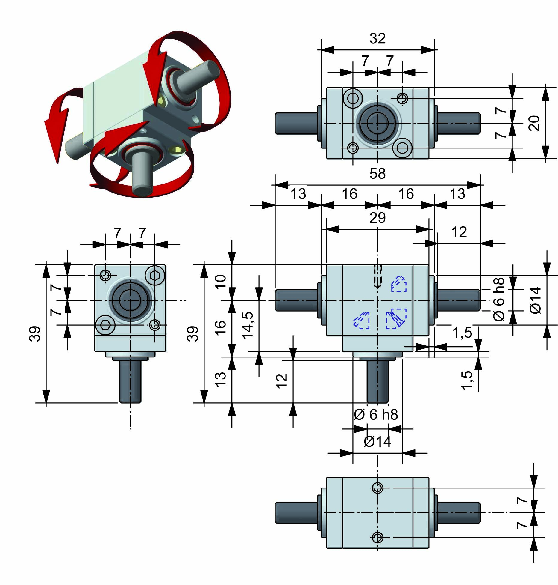 |
| VERSIONS ⟪B⟫ - M-F-F |
 |
| VERSIONS ⟪B⟫ - F-M-M |
 |
| VERSIONS ⟪B⟫ - F-F-F |
 |
| VERSIONS ⟪C⟫ - M-M-M con rotazione contraria |
 |
| VERSIONS ⟪C⟫ - M-F-F con rotazione contraria |
 |
| VERSIONS ⟪C⟫ - F-M-M con rotazione contraria |
 |
| VERSIONS ⟪C⟫ - F-F-F con rotazione contraria |
 |
| CONFIGURATION AND DIRECTION OF ROTATION | |||
| ⟪A⟫ | ⟪B⟫ | ⟪C⟫ | |
 |
|||
|
The direction of rotation depends from the configuration and from the positioning; see "Overall dimensions" . |
|||
|
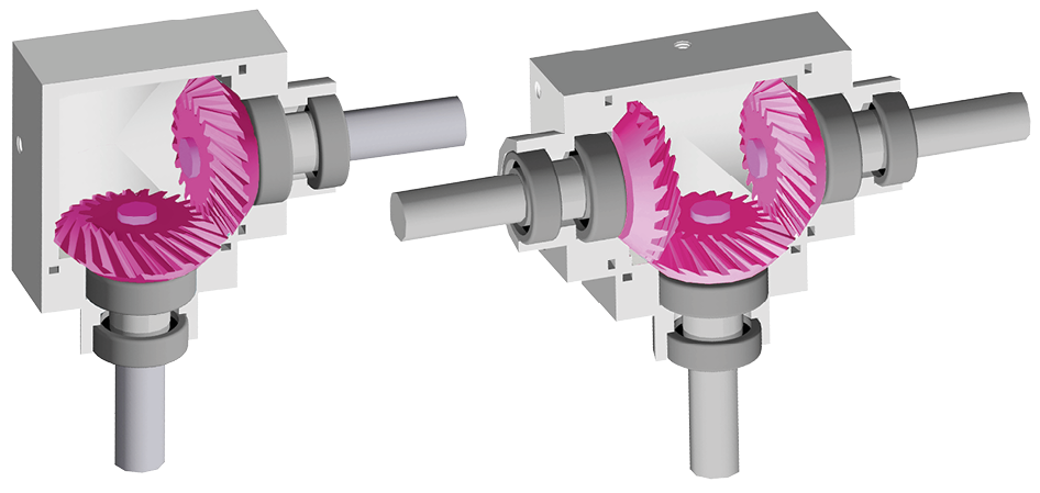
REPRESENTATION OF BEVEL GEARS |
|||
|
Straight bevel gears |
Spiral bevel gears |
||
 |
 |
||
|
Suitable for moderate loads and speeds |
Suitable for loads up to 30% higher and high speeds | ||
|
REPRESENTATION OF DESIGN CONFIGURATION |
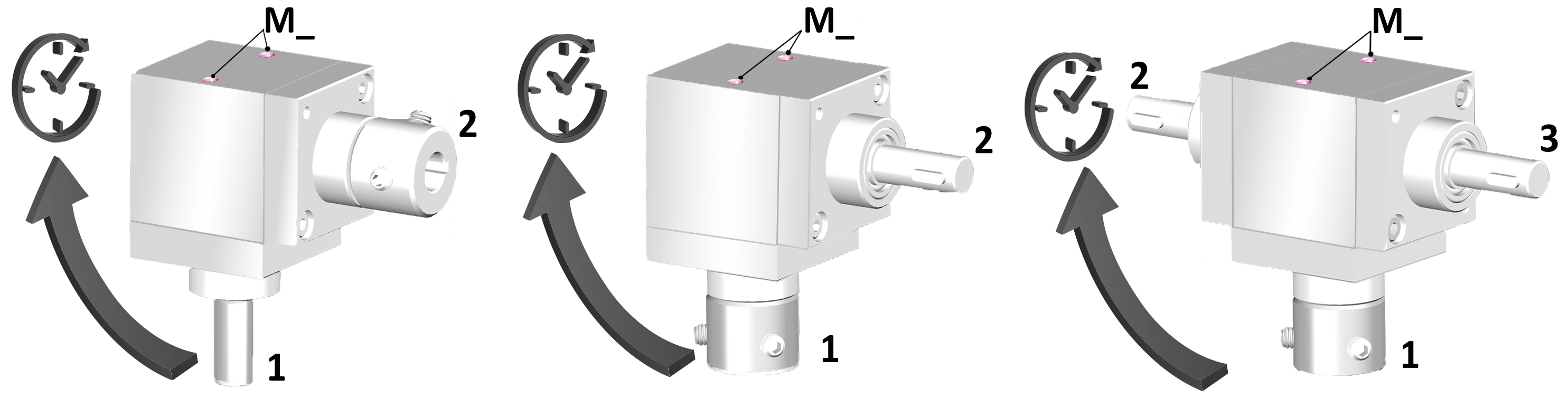 |
|
The desing configuration is determined by the shaft1always shown on the opposite side of the fixing bores M_, the others shaft are defined following the clockwise direction. |
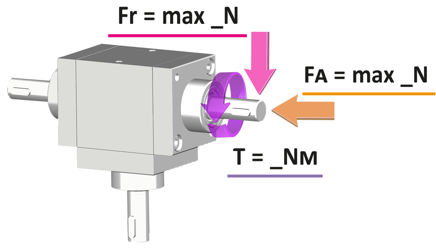
| REPRESENTATION OF LOADS | ||
|
«B» |
«D» |
|
 |
 |
|
| Fr = radial load 75 N The radial load acts in a perpendicular direction to the shaft Fa = axial load 7 N The axial load (in pull or push) acts in the same direction of the shaft T = torque 2 Nm |
||
|
Note: a radial load (ex. belt tension) can only be applied to the long shaft of the «B» and «D» versions; otherwise, a support must be provided. |
||
|
GREASE FITTING |
||
|
Gearboxes with 2 shafts |
Gearboxes with 3 shafts |
|
 |
 |
|
|
Recommended if work conditions exceed the parameters, to extend unit lifespan, or for difficult-to-reach positions. Lubricant must be replenished at variable intervals (consult Tech Dept). Standard position shown; alternative positions available on request. |
||


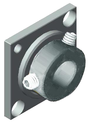
COUPLING BUSHES 2 piece bushing to couple gearboxes and shafts.
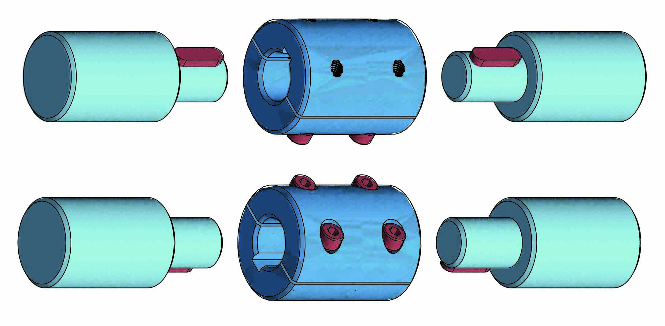
Available bores Ø: 6 - 8 -10 -14.
➜ for more complete information, see BT
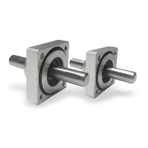
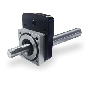
Flanged supports with extension shaft for coupling with position indicators.
➜ for more complete information, see Flanged supports
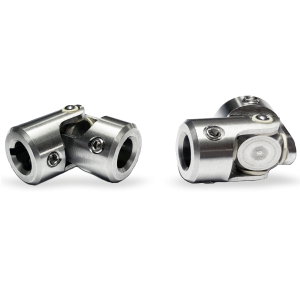
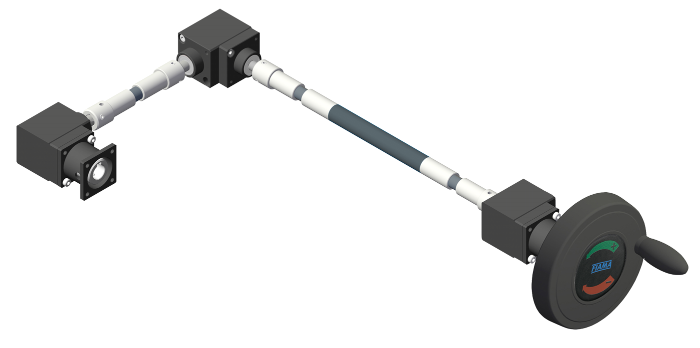
The «GC» and «GCC» cardan joints used for the transmission of torque and movement of non-aligned elements.
Main features: universal application, high reliability, maintenance free, extremely precise and ease-of-use.
• Case entirely machined from solid, in stainless steel AISI303.
• Suitable for intermittent (UI) and continuous movements (UC).
• Maximum working angle 45 °.
➜ for more complete information, see GC and GCC


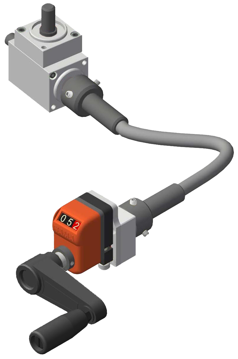
• 3 digits counter (standard red digit indicates decimals; on request 2 red digits for hundredths or 3 black digits for mm). Reading until 999. Digit height 6 mm
• Particularly suitable for little adjustments in small spaces.
• Standard shaft bore Ø8, Ø10 or Ø12.
➜ for more complete information, see OP2


The FL-M machine-side coupling flange, compatible with any configuration and shaft (male or female) of the gearbox, ensures a stable and precise coupling, minimizing vibrations and ensuring correct alignment between the connected components.
Made of black anodized aluminum, it is coordinated with the gearbox case, also in black
| FL-M | |||
 |
| Configuration examples | |
| Gearbox with 2 shafts | Gearbox with 3 shafts |
 |
|

Male shaft with flange MØ8x55 FL-OP2, compatible with any configuration and shaft of the gearbox, connects the position indicator, whether mechanical or electronic, to the gearbox. This combination enables precise and monitored position adjustment, increasing stability and accuracy of readings. Made of black anodized aluminum, it is coordinated with the gearbox case, also in black.
|
MØ8x55 FL-OP2 |
|
 |
|
| Configuration examples | |
|
Gearbox with 2 shafts |
Gearbox with 3 shafts |
 |
|
Photogallery


Richiedi l'accesso
| OUTPUT TORQUE WITH RATIO 1/1 | |||
 |
|||
| Efficiency = 90% | |||
- Tm = maximum torque in Nm
- dc = bevel gears
- dsp = spiral gears


