




66/5
Gearboxes for intermittent use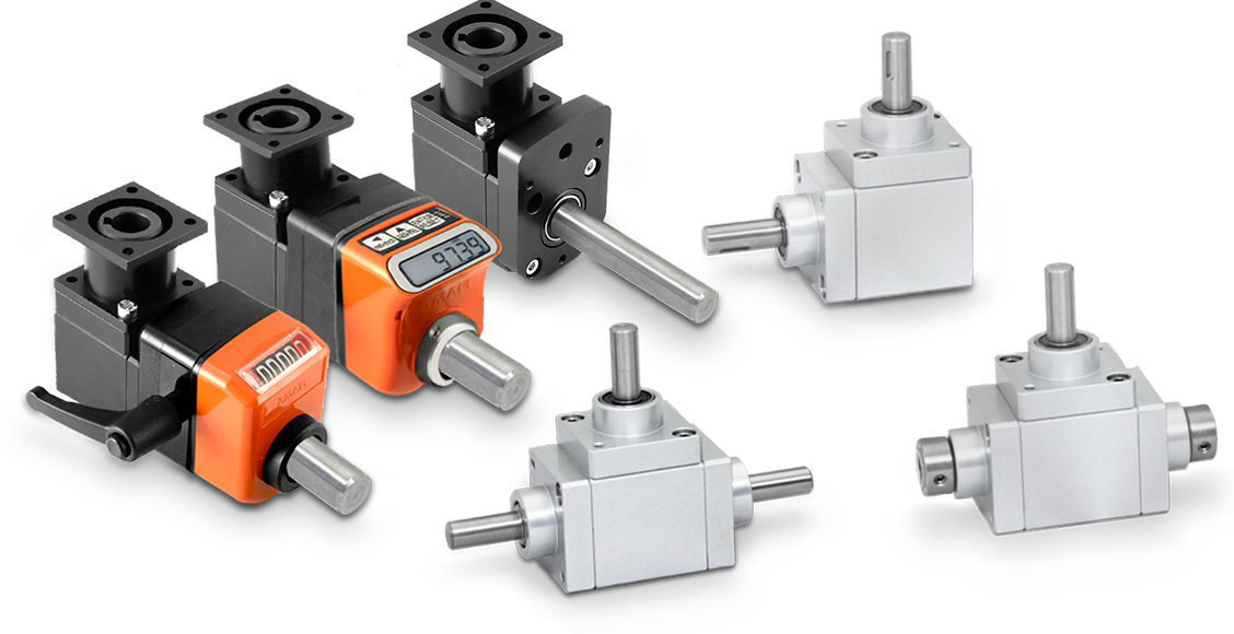
|
• Available transmission ratios: 1:1 - 1:2 (standard) - 2:1 (available in versions «A»-«B»-«C»). |
||
|
• Ratios 1/2 and 2/1 are only available with spiral gears. |
||
|
• Aluminium case, anodised; stainless steel shafts (standard). |
||
|
• Torque 12 Nm. Radial load 25 kg - axial load 2,5 kg. |
||
|
• Models: |
||
|
- Version «A» with 2 outputs; weight 330 g. |
||
|
- Version «B» with 3 outputs; weight 520 g. |
||
|
- Version «C» (opposite rotation) with 3 ouputs; weight 535 g. |
||
|
- Version «D» with 3 outputs, 2 through hollow shafts; weight 520 g. |
||
|
- Version «E» with 4 outputs; weight 600 g. |
||
|
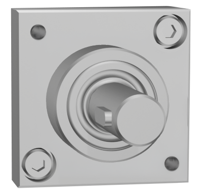
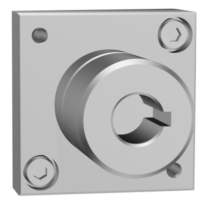
• Standard output shafts: M = male Ø10 / F = female Ø10. |
||
|
Available on request: |
|
|
|
▪ Output shafts: male Ø14 / female Ø12 - Ø14 in versions «A»-«B»-«C». |
||
|
▪ Case in stainless steel AISI 303. |
||
|
▪ Models with spiral bevel gears are available in all versions with transmission ratio 1/1. |
||
|
▪ Machine-side coupling flange FL-M. |
||
|
▪ Male shaft flange for position indicators FL-OP/EP. |
Photogallery


|
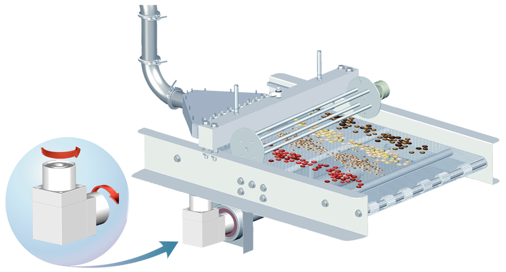
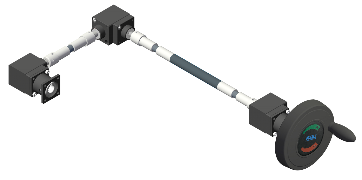
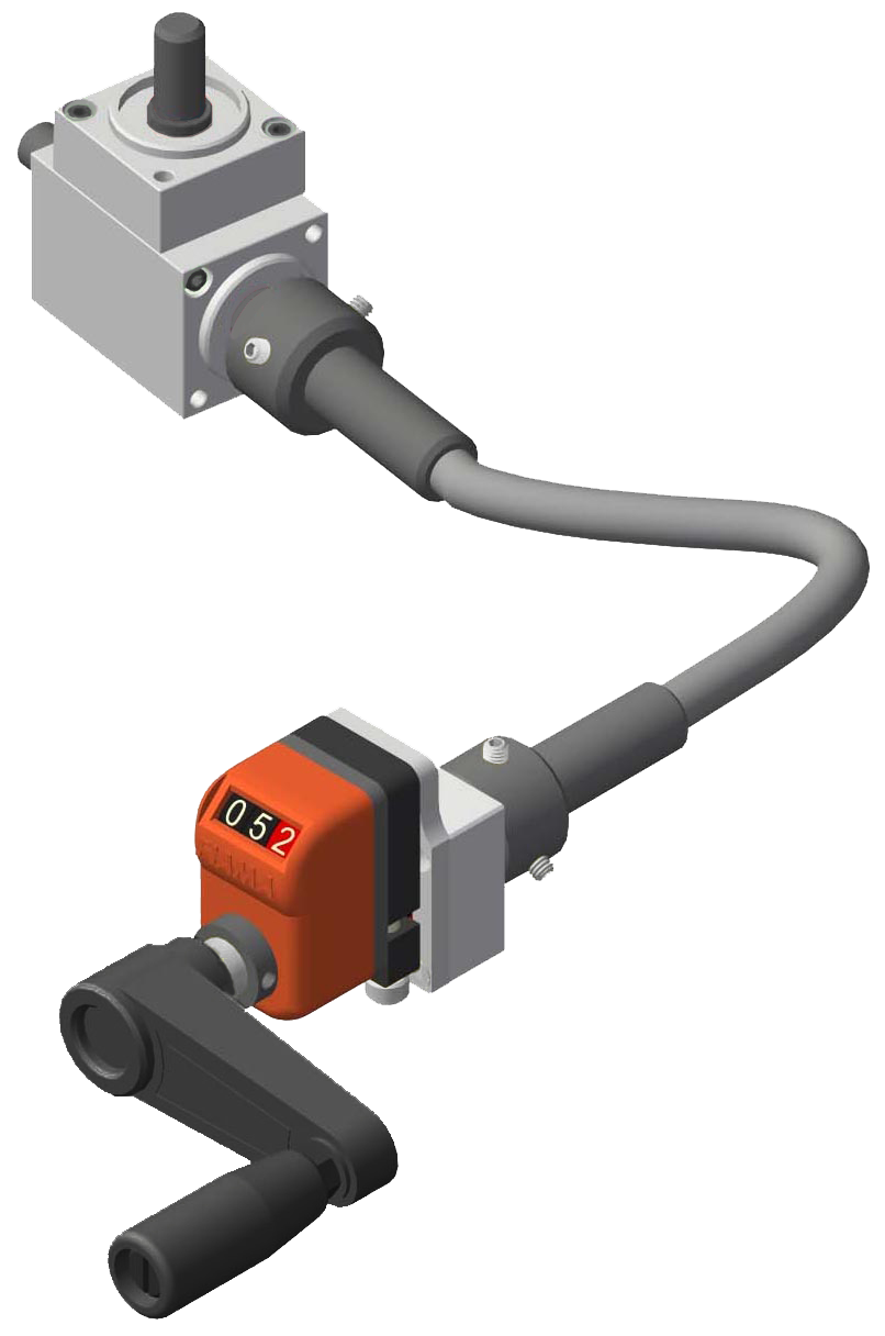
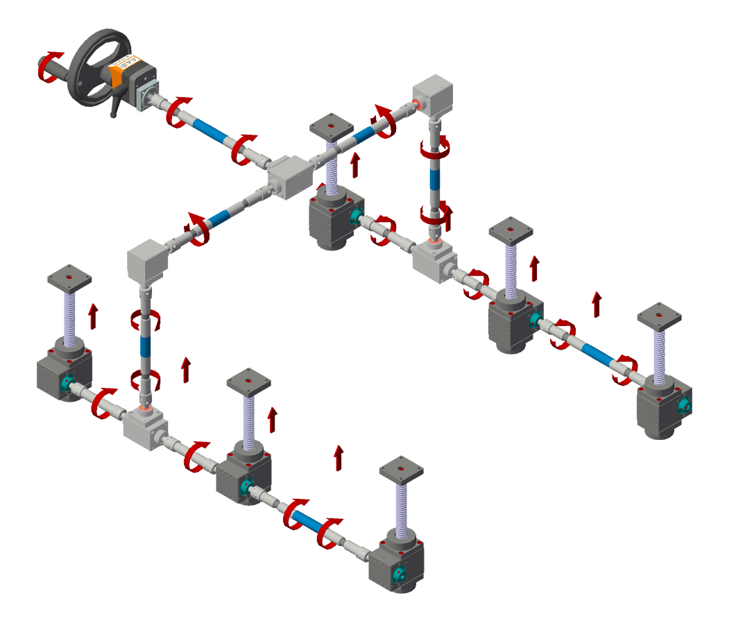
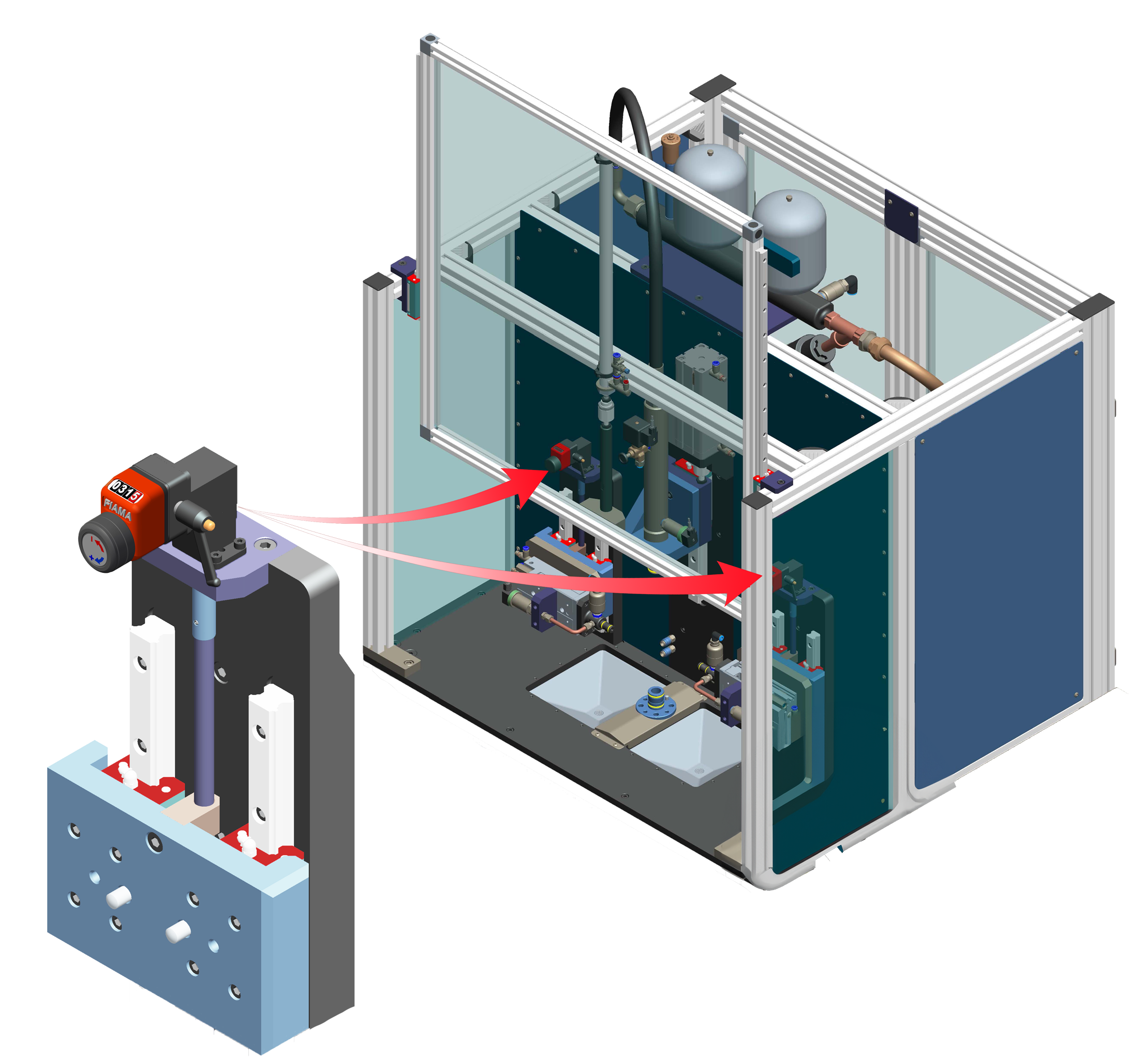
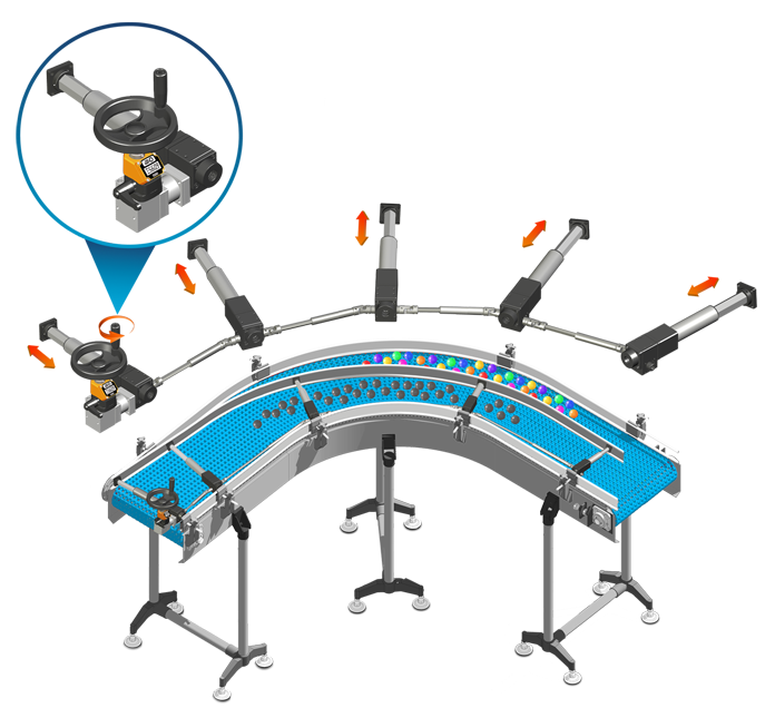
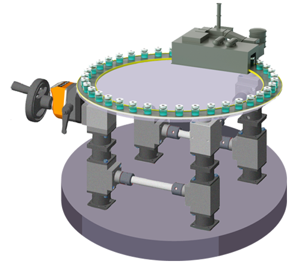
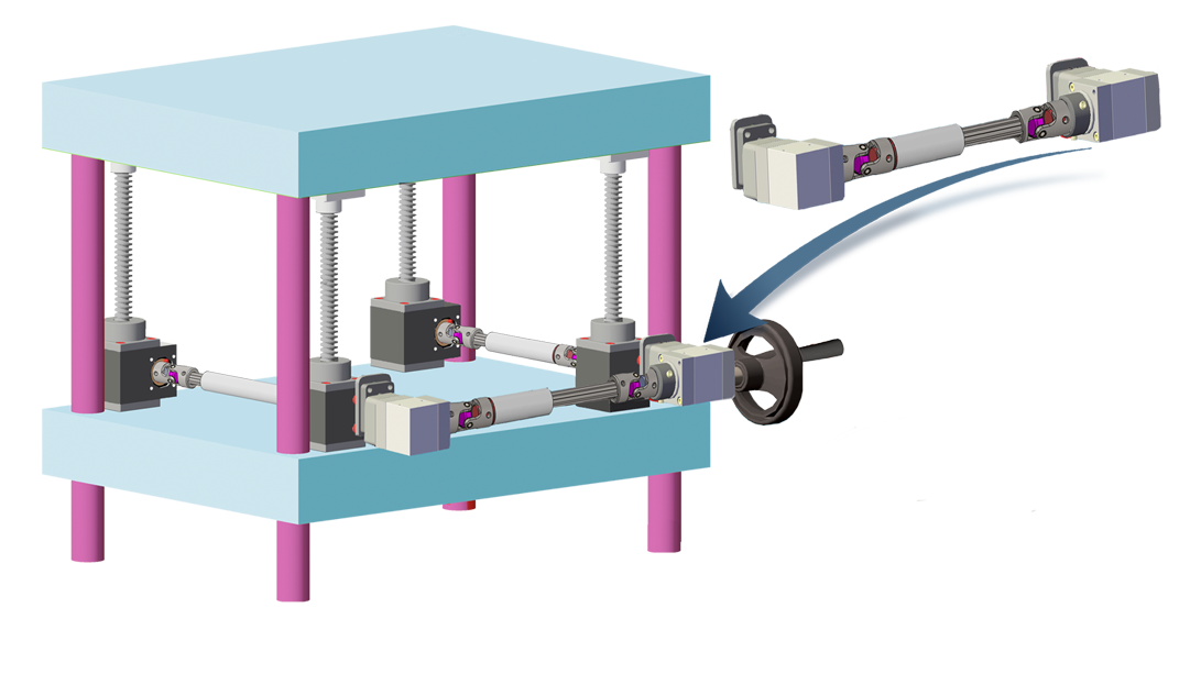
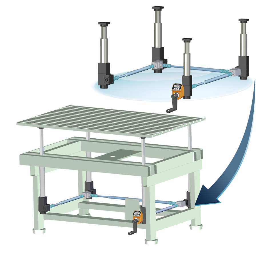
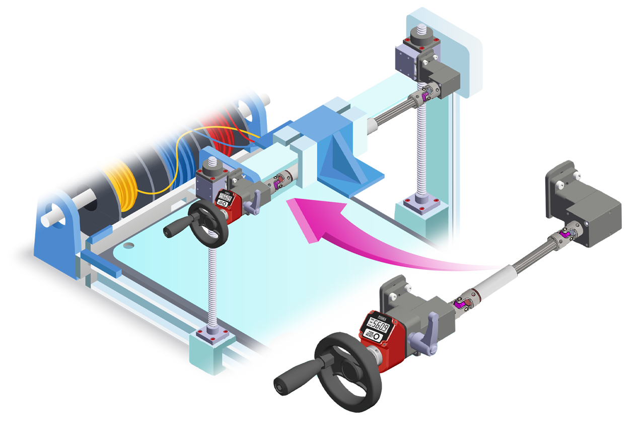
APPLICATION EXAMPLES |






| AVAILABLE SHAFTS |
| M = male |
 |
| F = female |
 |
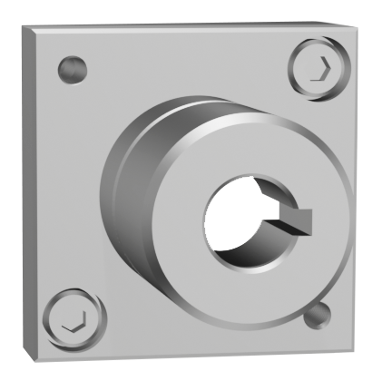
| F = female through shaft (available only on versione ⟪D⟫) |
 |
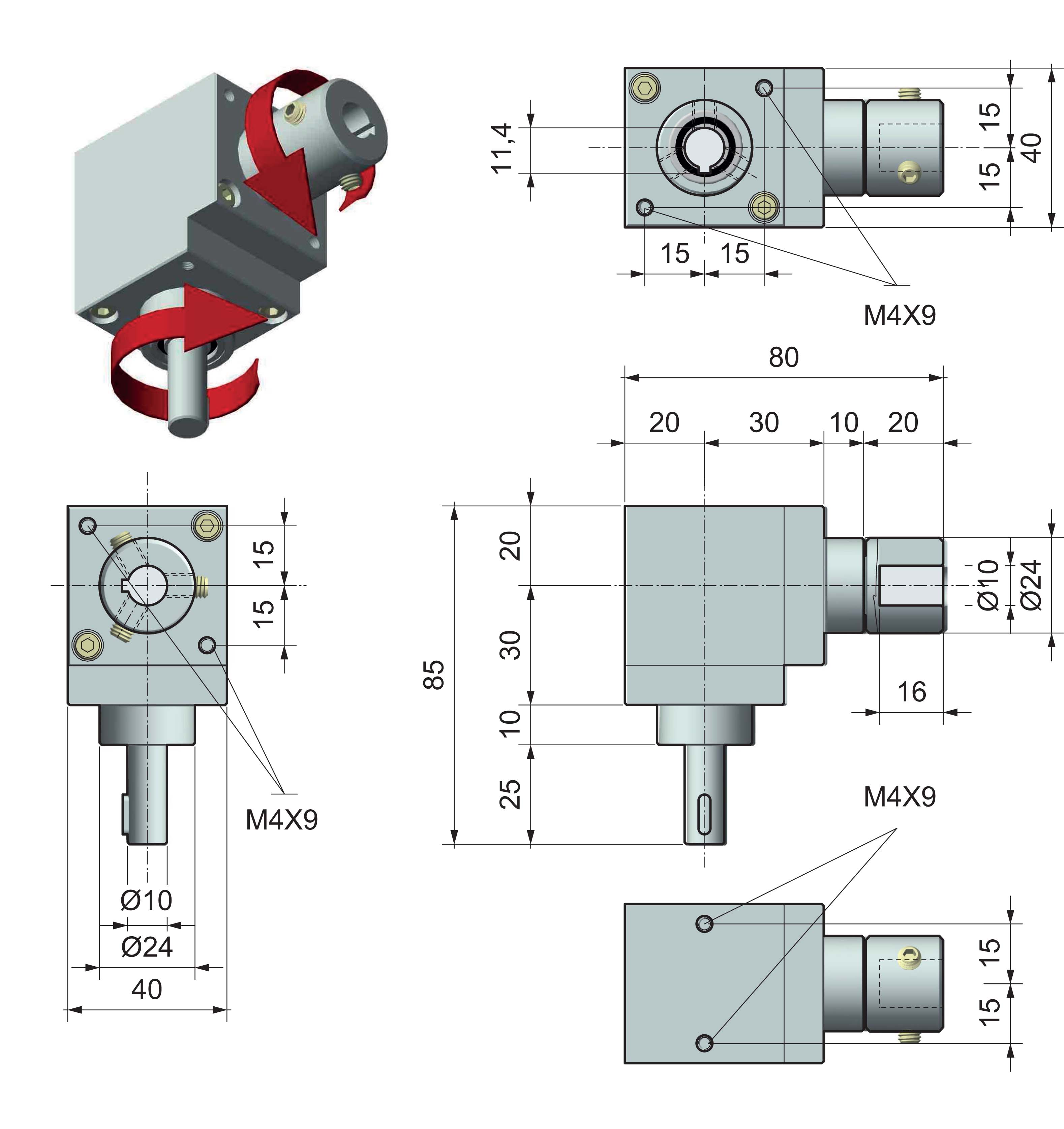
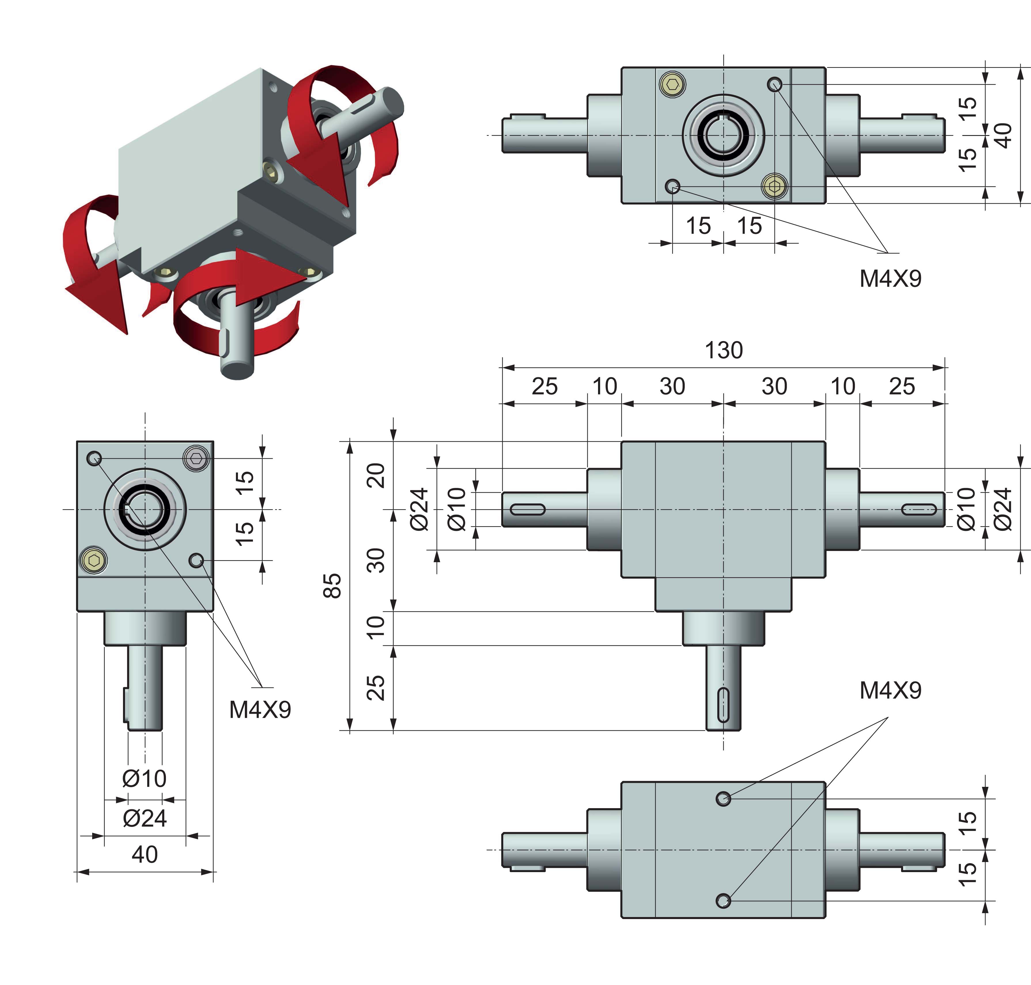
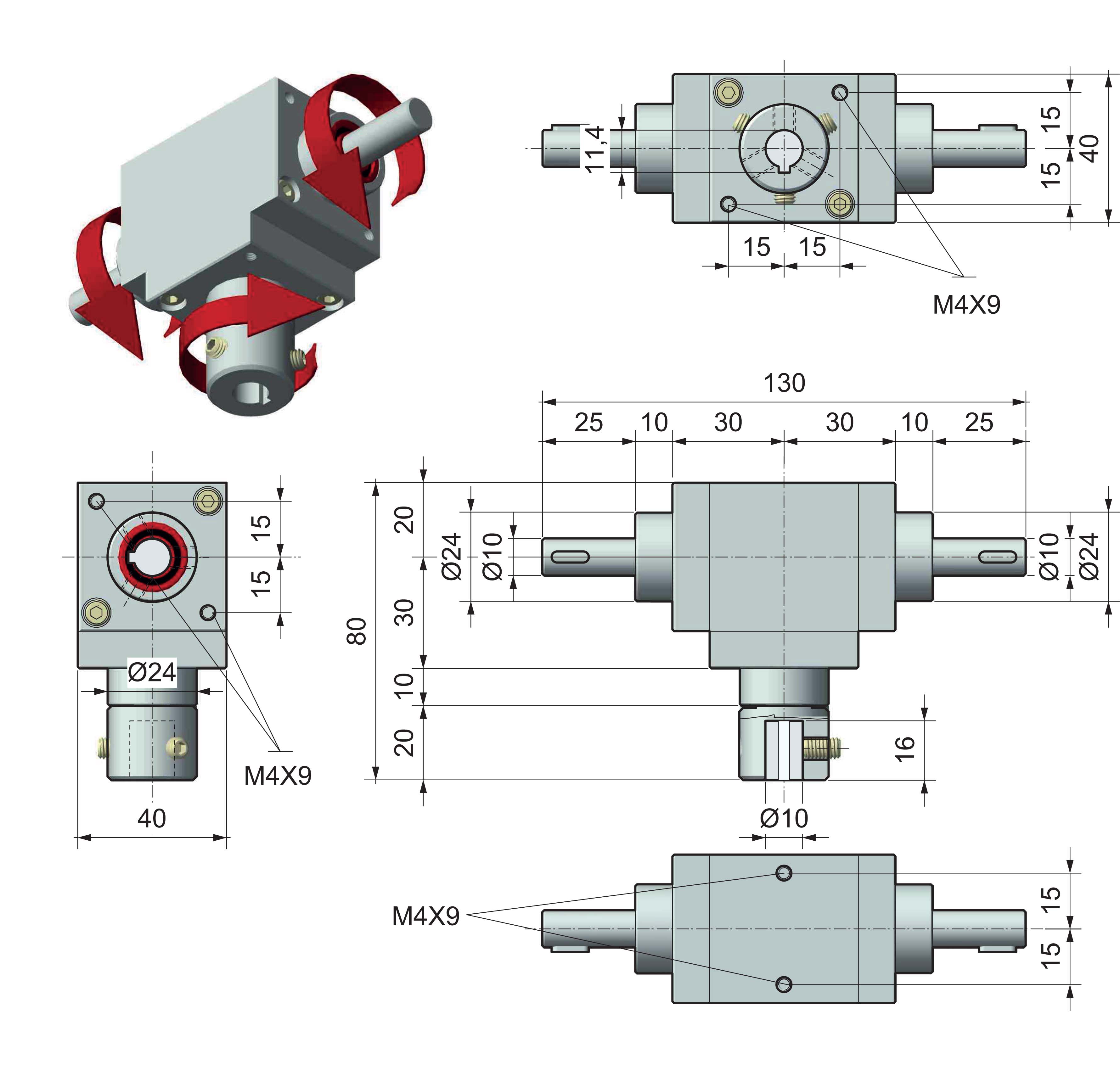
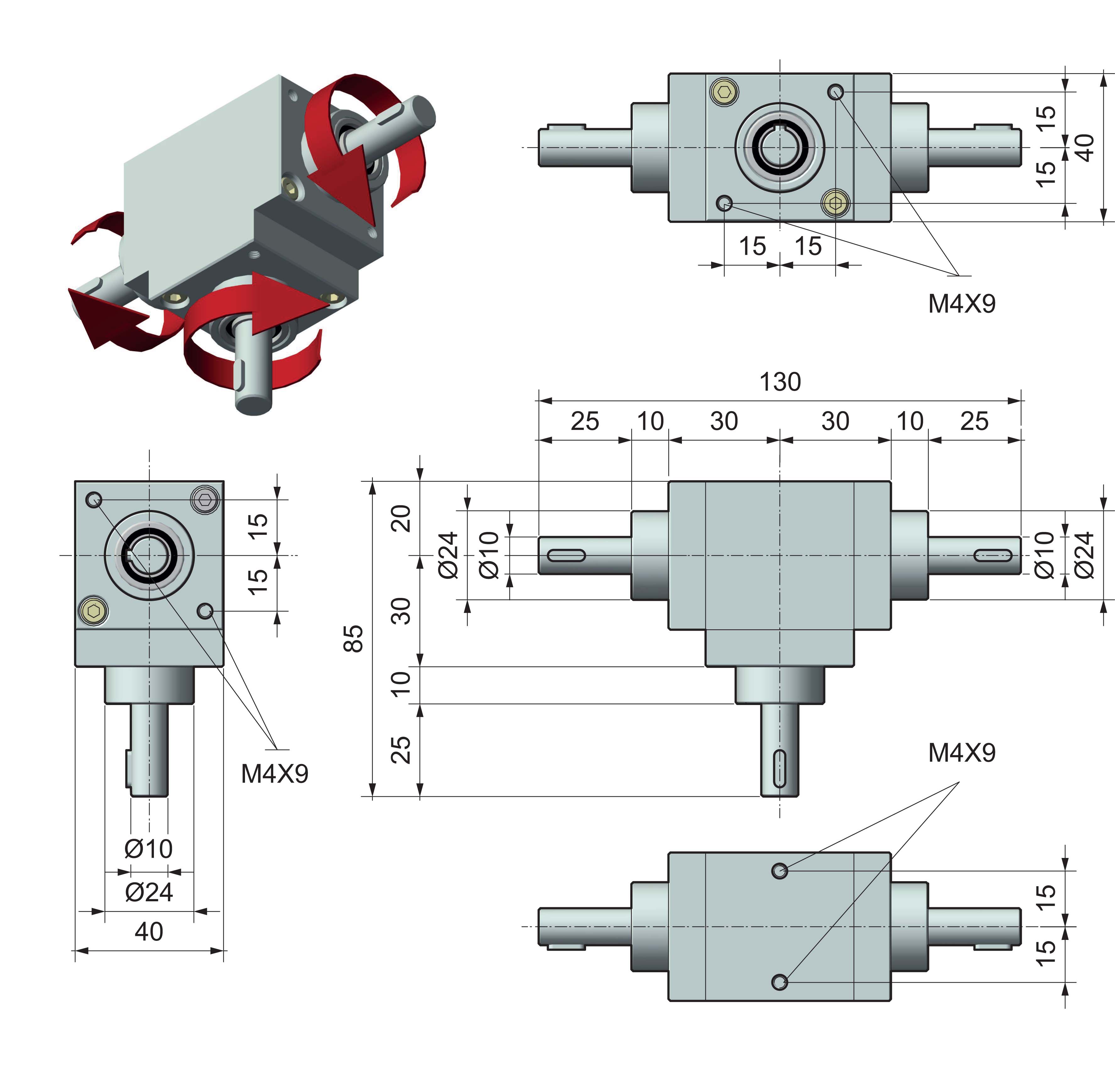
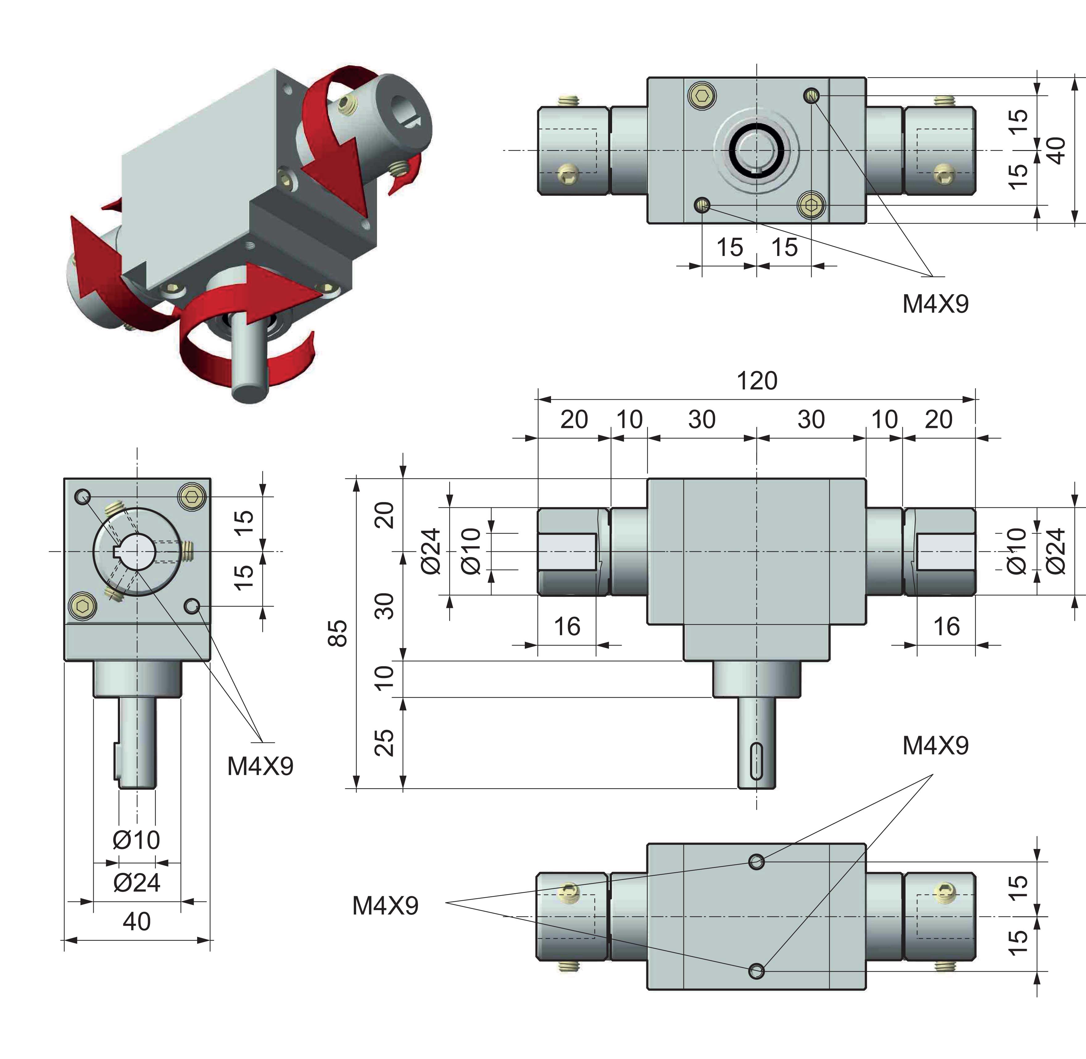
| DIMENSIONS |
| VERSION ⟪A⟫ - M-M |
 |
| VERSION ⟪A⟫ - M-F |
 |
| VERSION ⟪A⟫ - F-F |
 |
| VERSION ⟪B⟫ - M-M-M |
 |
| VERSION ⟪B⟫ - F-M-M |
 |
| VERSION ⟪C⟫ - M-M-M with opposite rotation |
 |
| VERSION ⟪C⟫ - M-F-F with opposite rotation |
 |
| VERSION ⟪C⟫ - F-M-M with opposite rotation |
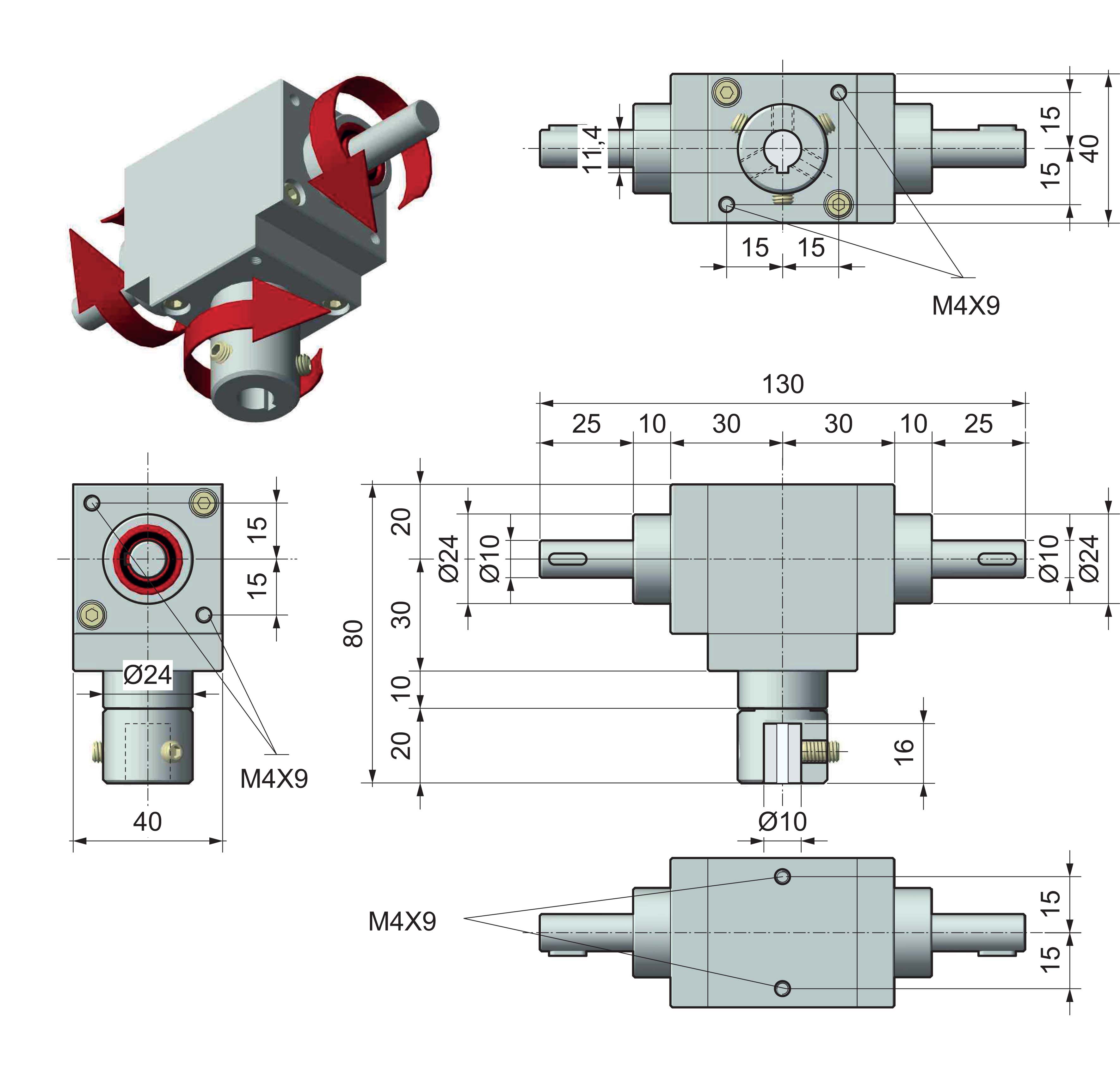 |
| VERSION ⟪C⟫ - F-F-F with opposite rotation |
 |
| VERSION ⟪D⟫ - M-F-F with through-hollow shaft |
 |
| VERSION ⟪D⟫ - F-F-F with through-hollow shaft |
 |
| VERSION ⟪D⟫ - F-F(ø10CH3)-F(ø10CH3) with through-hollow shaft |
 |
| VERSION ⟪D⟫ - M-F(ø10CH3)-F(ø10CH3) with through-hollow shaft |
 |
| VERSION ⟪E⟫ - M-M-M-M |
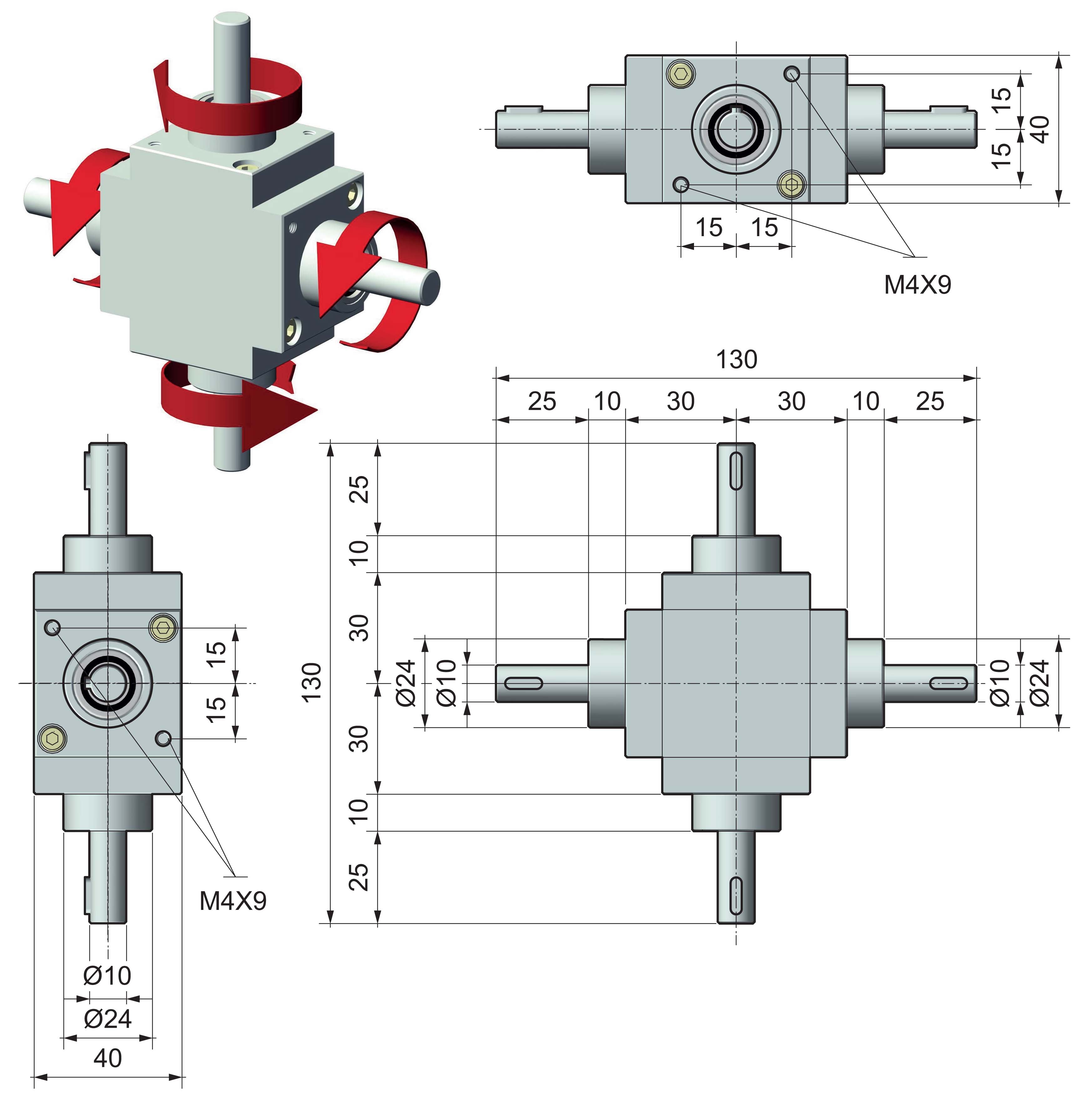 |
| VERSION ⟪E⟫ - F-F-F-F |
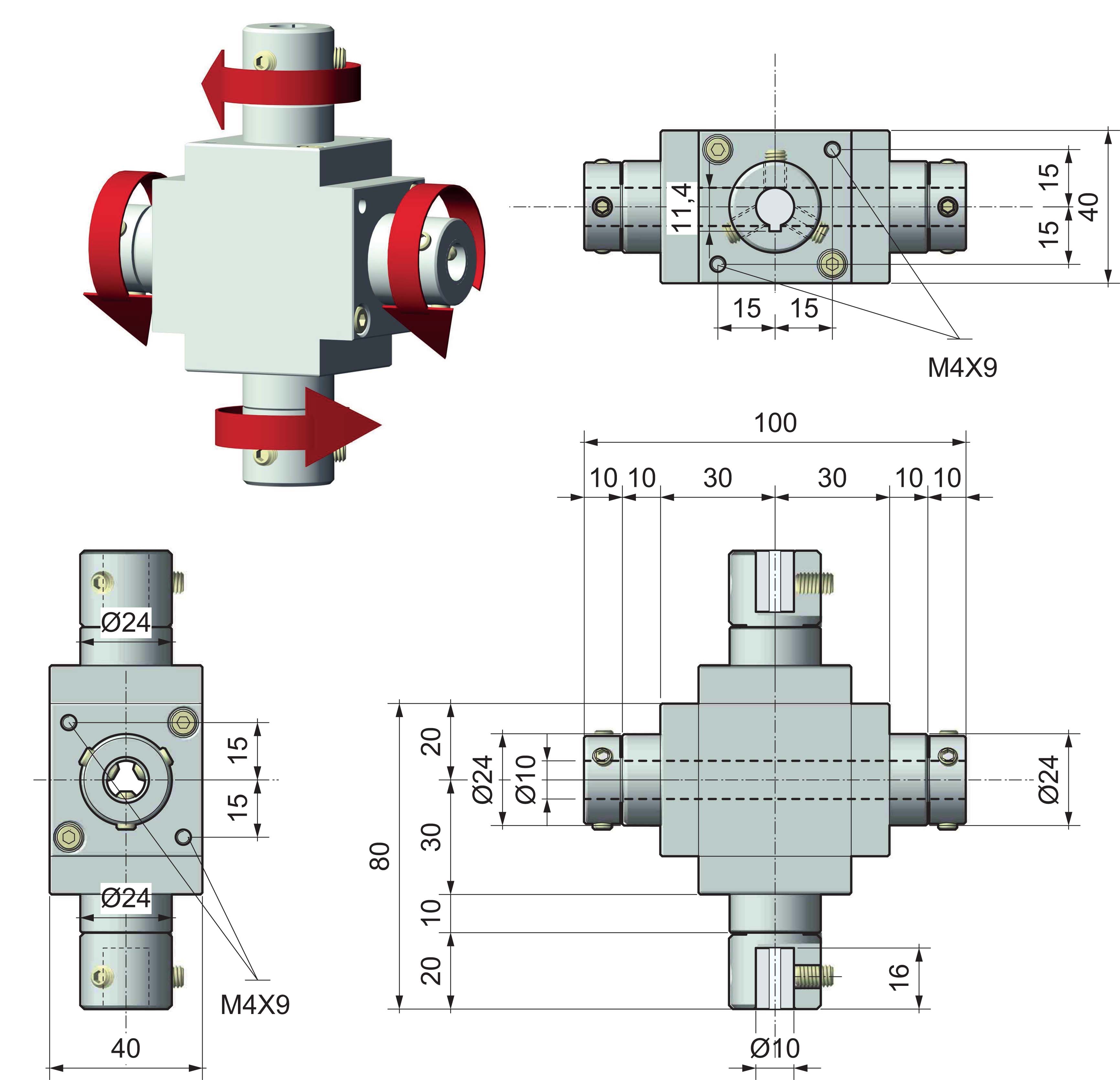 |
|
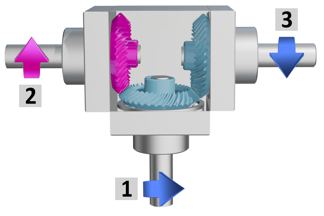
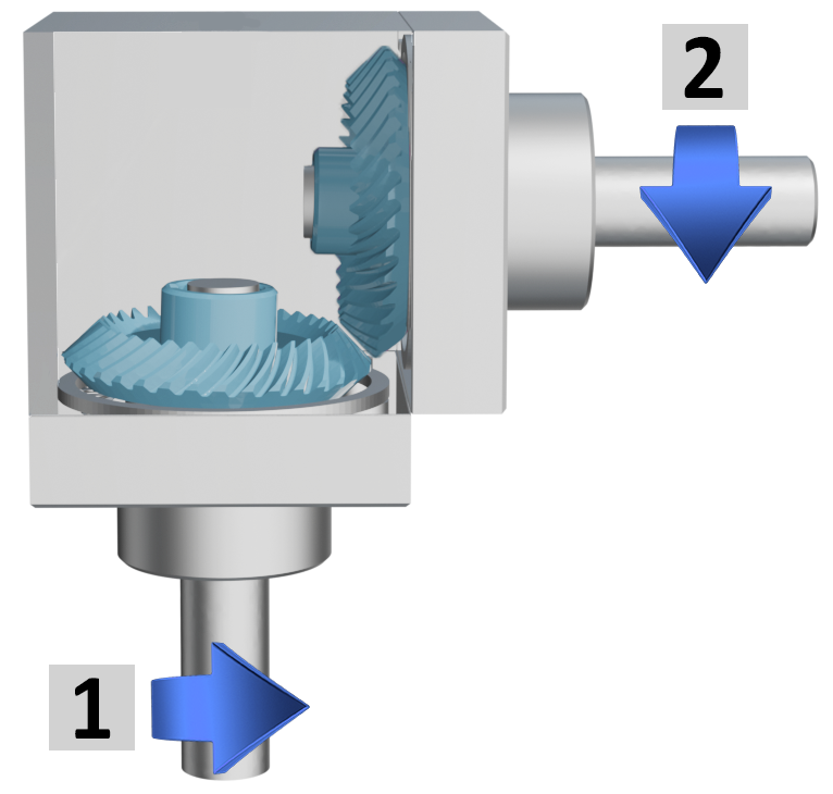
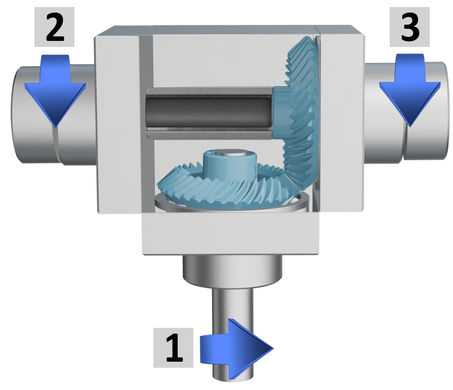
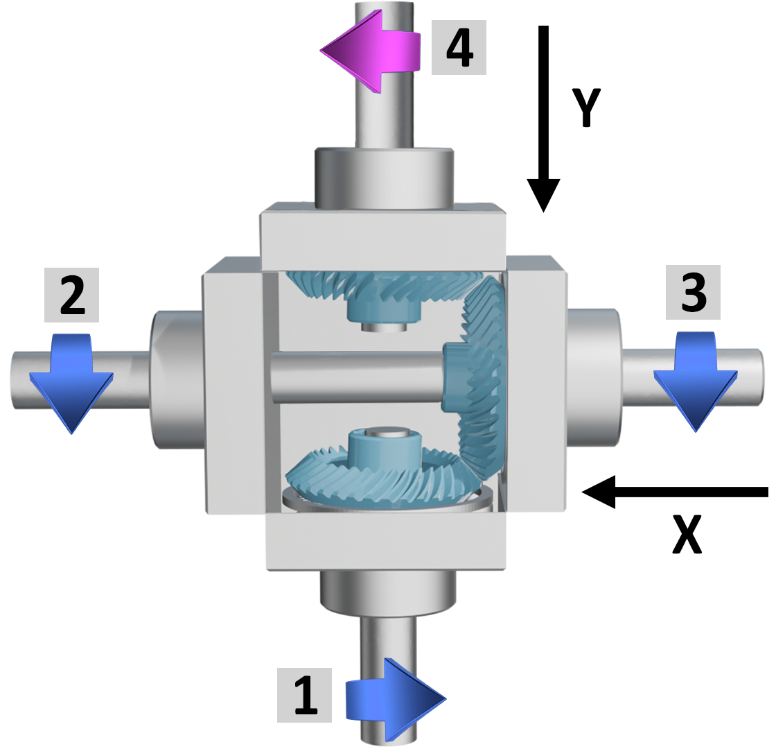
CONFIGURATION AND DIRECTION OF ROTATION |
Tab.1 |
||
| AVAILABLE VERSIONS | ||
| ⟪A⟫ | ⟪B⟫ | ⟪C⟫ |
|
|
 |
 |
|
2 outputs, same rotation direction |
3 outputs, same rotation direction |
3 outputs, 1 with opposite rotation directions |
| ⟪D⟫ | ⟪E⟫ |
|
|
|
|
3 outputs, 2 with through hollow shafts, same rotation direction |
4 outputs, same rotation direction on axis X, opposite on axis Y |
|
|
|
|
OUTPUT SHAFT IDENTIFICATION |
Tab.2 |
| AVAILABLE OUTPUT SHAFTS | ||||||||
| male = M |
female blind = F |
through female = F |
||||||
 |
 |
 |
||||||
|
Example with 2 outputs |
Example with 3 outputs |
 |
 |
|
|
|
|
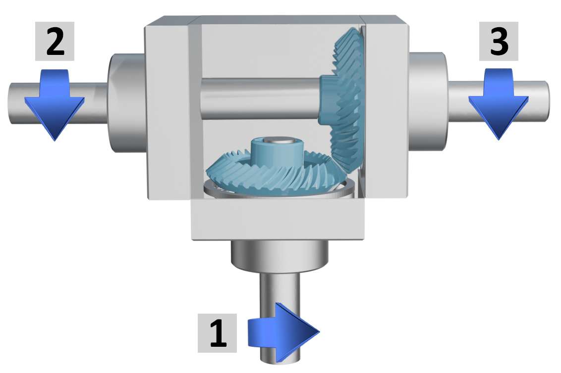
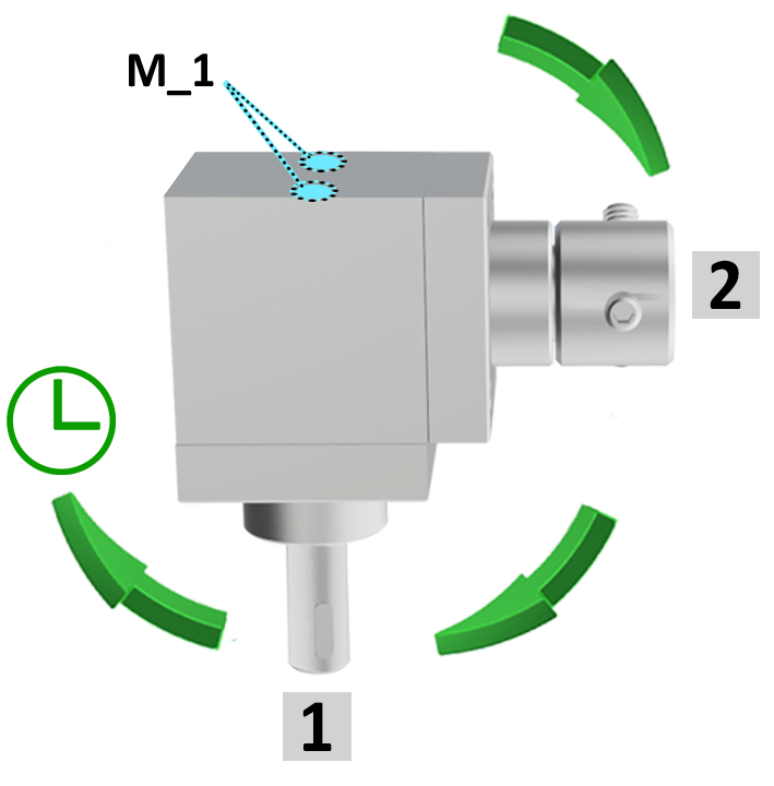
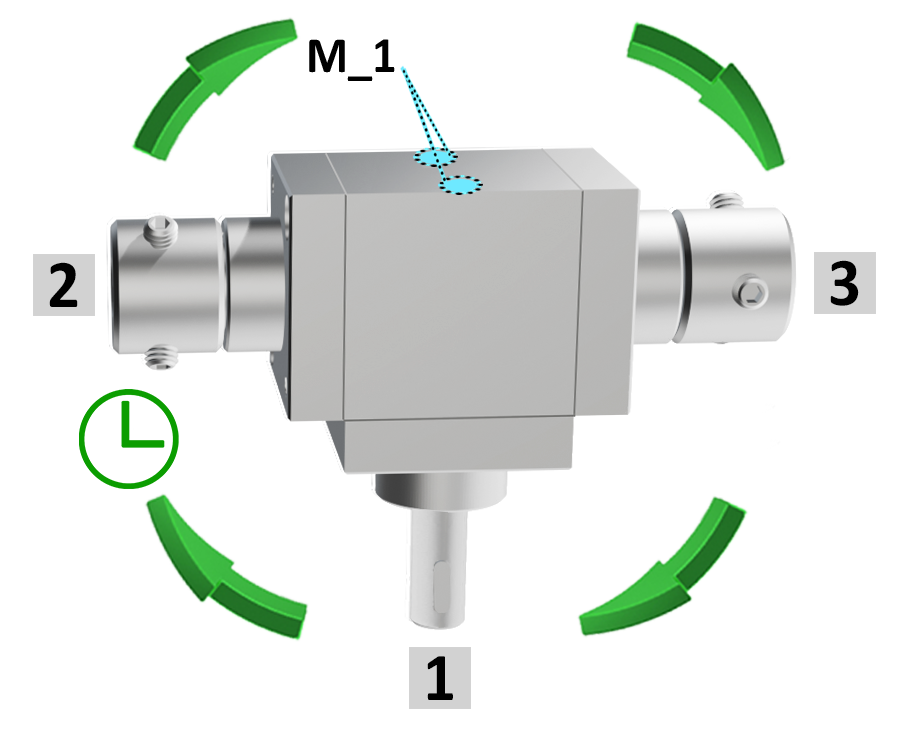
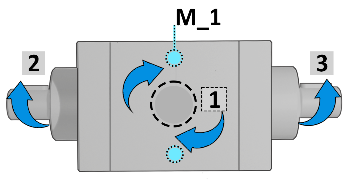
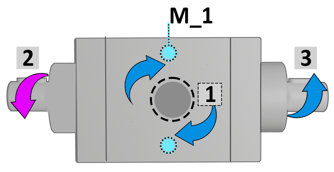
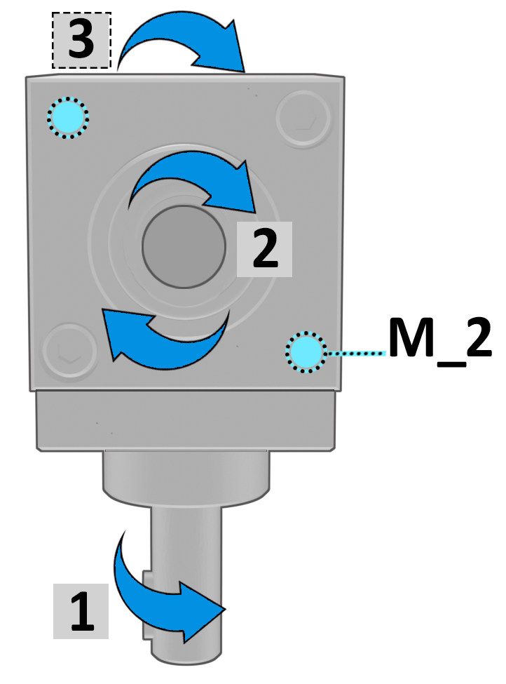
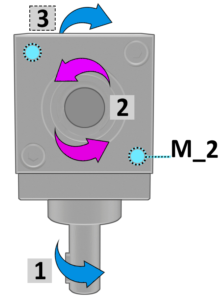
Shaft 1 is always shown on the side opposite the M_1 fixing bores and serves as the reference for determining: |
|
|
● the configuration |
|
|
● the direction of rotation |
|
|
● the gear ratio |
|
|
By convention, Shaft 1is shown rotating clockwise. The others shaft are defined following the clockwise direction. |
|
|
AVAILABLE TRANSMISSION RATIOS |
Tab.3 |
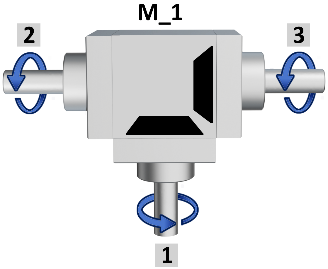
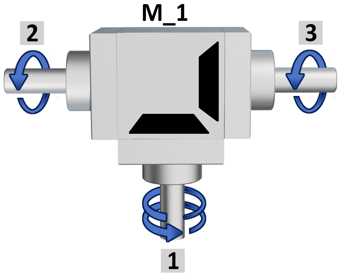
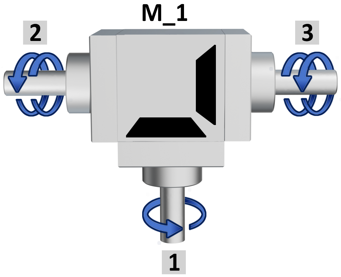
 The ratio is determined by the shaft1always shown on the opposite side of the fixing bores M_1. The ratio is determined by the shaft1always shown on the opposite side of the fixing bores M_1. |
||
| Ratio 1/1 | Ratio 1/2 | Ratio 2/1 |
 |
 |
 |
|
Example |
Example |
Example |
| Shaft 1 = 10 rpm | Shaft 1 = 10 rpm | Shaft 1 = 5 rpm |
| Shafts 2-3 = 10 rpm | Shafts 2-3 = 5 rpm | Shafts 2-3 = 10 rpm |
| not available in version D | ||
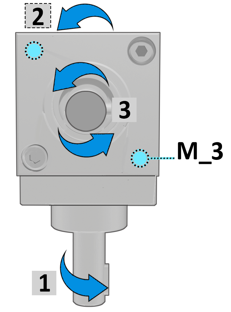
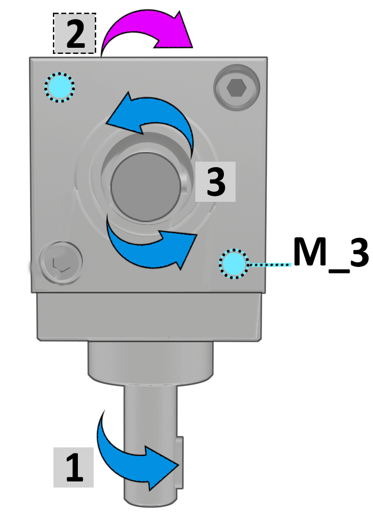
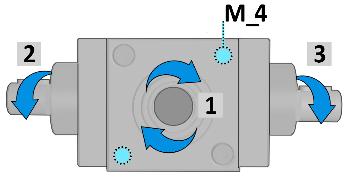
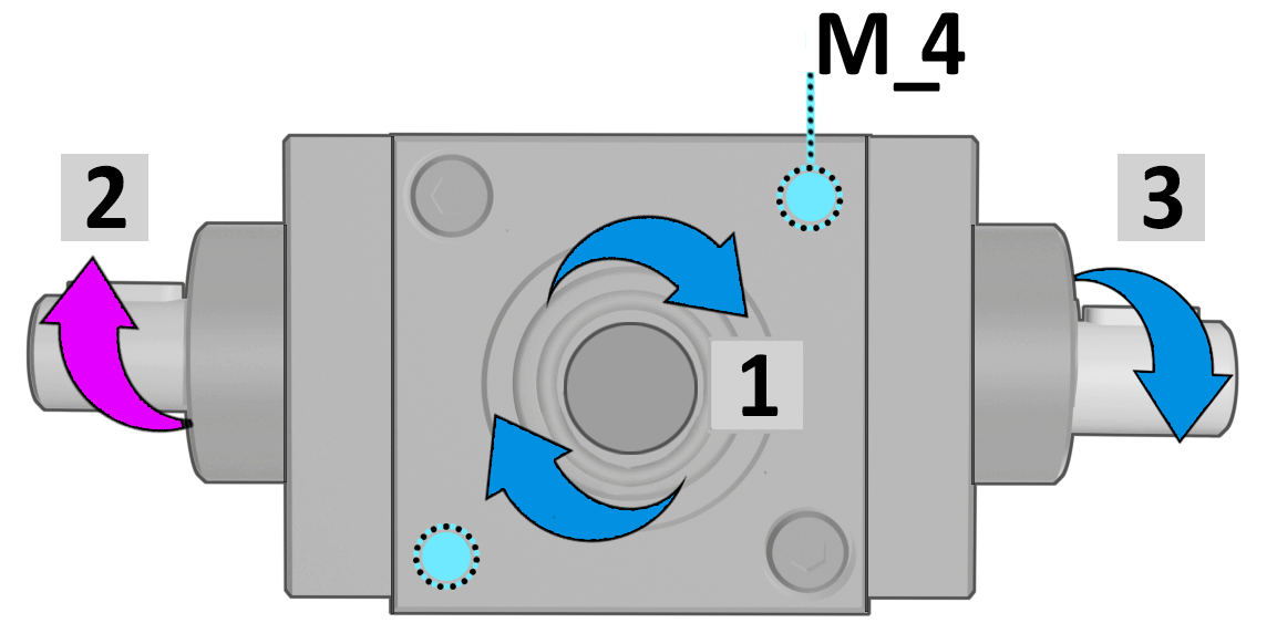
| M_ FIXING POSITIONS | Tab.4 |
|
|
| M_1 = top view. 0° | M_2 = right side view 90° | |||
 |
 |
+90° →DX |
 |
 |
| same rotation | opposite rotation | same rotation | opposite rotation | |
|
↑ +90° |
+90° ↓ |
|||
| M_3 = left side view 270° | M_4 = bottom view 180° | |||
 |
 |
+90° ← SX |
|
|
| same rotation | opposite rotation | same rotation | opposite rotation | |


COUPLING BUSHES 2 piece bushing to couple gearboxes and shafts.
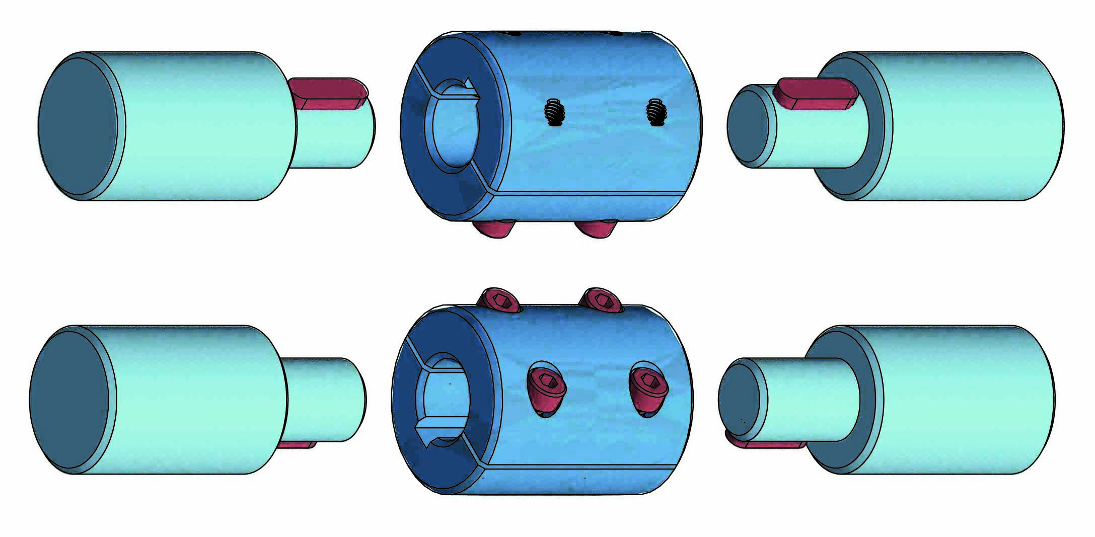
Available bores Ø: 6 - 8 -10 -14.
➜ for more complete information, see BT
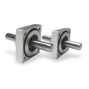
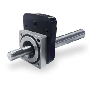
Flanged supports with extension shaft for coupling with position indicators.
➜ for more complete information, see Flanged supports
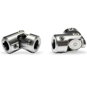
The «GC» and «GCC» cardan joints used for the transmission of torque and movement of non-aligned elements.
Main features: universal application, high reliability, maintenance free, extremely precise and ease-of-use.
• Case entirely machined from solid, in stainless steel AISI303.
• Suitable for intermittent (UI) and continuous movements (UC).
• Maximum working angle 45 °.
➜ for more complete information, see GC and GCC


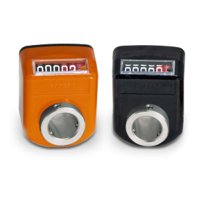
• 4 digits counter (standard red digit indicates decimals; on request 2 red digits for hundredths or 4 black digits for mm). Reading until 9999.Digit height 5 mm
• Standard shaft bore: ø14H7; other bores, smaller than 14 with reducing bush.
➜ for more complete information, see OP3
• 5 digits counter (standard red digit indicates decimals; on request 2 red digits for hundredths or 5 black digits for mm).
• Readings until 99999. ‘Lens to improve the reading’: digit height 7 mm.
• Standard shaft bore ø20 (OP7) or ø25 bore (OP7F25). Other holes smaller than 20 with reducing bush.
➜ for more complete information, see OP7
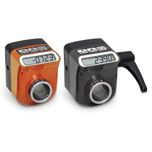
• Measures linear or angular movements, applicable to many types of industrial
• Simple assembly through the hollow shaft
• Powered by long battery life, easy replacement from the front
➜ for more complete information, see EP7

The EP3 electronic indicator allows monitoring of adjustments to eliminate errors and a precise reading of linear or angular displacements.
• 100% interchangeable with mechinal indicator OP3.
• Powered by a long-life battery, easy replacement from the front.
• Hollow shaft made of stainless steel; shock, vibration and dirt resistant plastic case.
➜ for more complete information, see EP3


The flange FL-M, compatible with any configuration and output shaft (male or female) of the gearbox, ensures a stable and precise coupling, minimizing vibrations and ensuring correct alignment between the connected components. Made of black anodized aluminum, it is coordinated with the gearbox case, also in black.
| FL-M | |
 |
|
| Configuration examples | |
|
Gearbox with 2 ouputs |
Gearbox with 3 ouputs |
 |
|
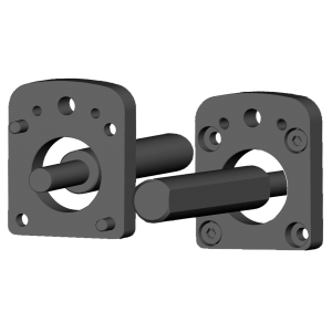
Male shaft with flange MØ14x80 FL-OP3/EP3, compatible with any configuration and output shaft of the gearbox, connects the position indicator, whether mechanical or electronic, to the gearbox. This combination enables precise and monitored position adjustment, increasing stability and accuracy of readings. Made of black anodized aluminum, it is coordinated with the gearbox case, also in black.
| MØ14x68 FL-OP3/EP3 | |
 |
|
| Configuration examples | |
|
Gearbox with 2 ouputs |
Gearbox with 3 ouputs |
 |
|
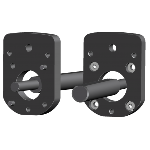
Male shaft with flange MØ14x80 FL-OP7/EP7, compatible with any configuration and output shaft of the gearbox, connects the position indicator, whether mechanical or electronic, to the gearbox. This combination enables precise and monitored position adjustment, increasing stability and accuracy of readings. Made of black anodized aluminum, it is coordinated with the gearbox case, also in black.
| MØ14x80 FL-OP7/EP7 | |
 |
|
| Configuration examples | |
|
Gearbox with 2 ouputs |
Gearbox with 3 ouputs |
 |
|
Photogallery


Richiedi l'accesso
| OUTPUT TORQUE WITH RATIO 1/1 |

| OUTPUT TORQUE WITH RATIO 1/2 |

| OUTPUT TORQUE WITH RATIO 2/1 |

| Efficiency = 90% |
| - Tm = maximum torque in Nm |
| - dc = bevel gearing |
| - dsp = spiral gearing |


