
AF-M
Flexible couplings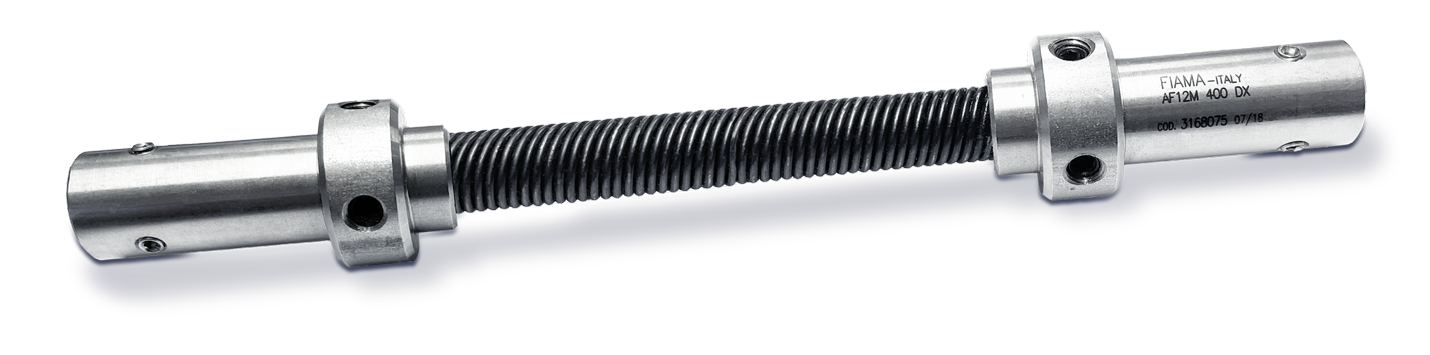
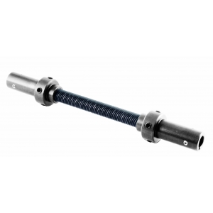
FIAMA flexible shafts are mechanical devices that are used to transfer, with the highest precision, a rotary movement between two non-aligned shafts. Installation is extremely simple by connecting the two terminals (various types are available) without the need for other supports.
Terminals made of stainless steel AISI 303.
➜ Protective cover made of “Rilsan” for lengths over 400mm.
• Limited dimensions, weight, inertia
• Robust and highly reliable, not subject to wear and maintenance
• Excellent compensation of misalignments without free play
• Compact space requirements, max recommended length 400mm
• Same rotation speed of both shafts, silent operation, dampening of vibrations and shocks.
The limited cost and easy installation allow various solutions, even in heavy-duty applications such as:machine tools, equipment automation, automatic machines, robots, etc.
Photogallery


|
DIMENSION TABLE |
|||||||||
|
|
|||||||||
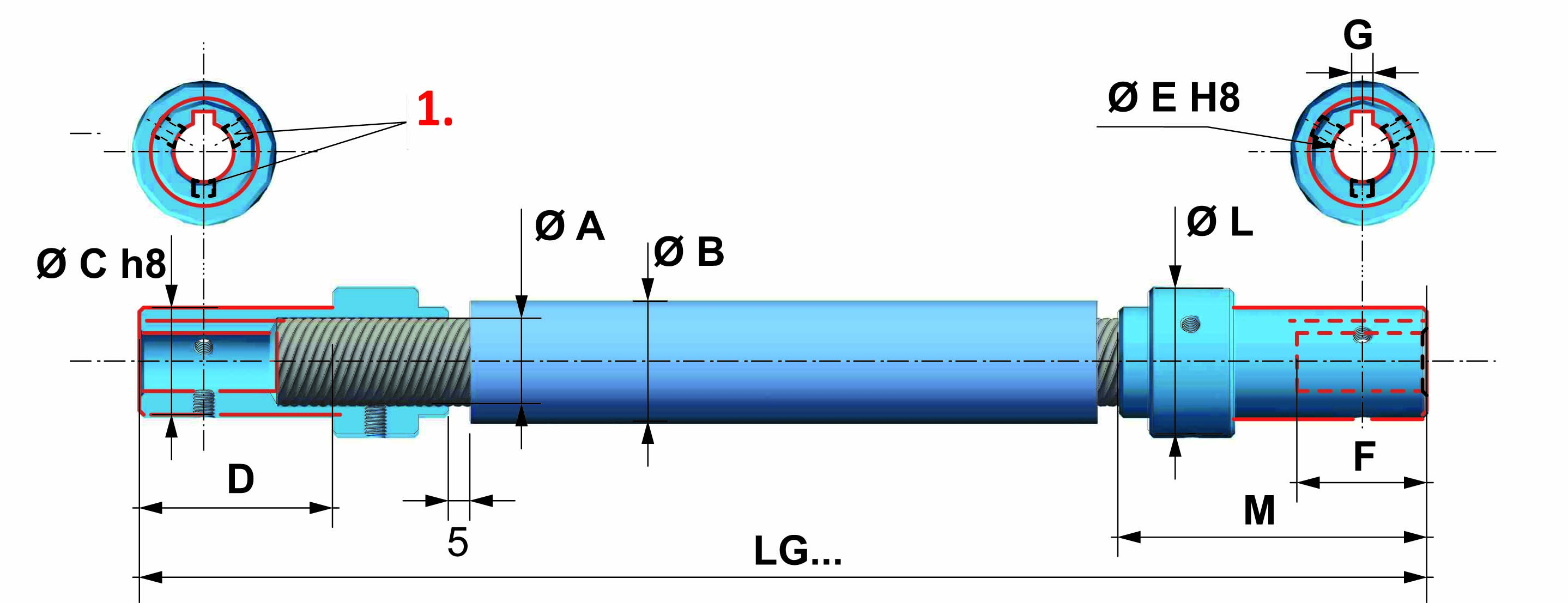
| VERSION | FLEXIBLE SHAFT | EXTERNAL COVER | TERMINAL | EFFECTIVE (L) | INNER TERMINAL | BORE DEPTH |
KEYWAY |
COVER TERMINAL | TERMINAL (L) |
| Ø A | Ø B | Ø C | D | Ø E | F | G | Ø L | M | |
| AF6M | 6 | 12 | 12 | 30 | 6 | 20 | = | 15 | 45 |
| AF8M | 8 | 14 | 15 | 30 | 8 | 20 | = | 20 | 45 |
| AF12M | 12 | 20 | 17 | 37 | 10 | 26 | 3 | 26 | 56 |
| AF15M | 15 | 22 | 20 | 37 | 10 | 26 | 3 | 28 | 56 |
| AF20M | 20 | 35 | 25 | 45 | 14 | 32 | 5 | 34 | 72 |
| The data refers to length L=1000mm |


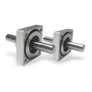
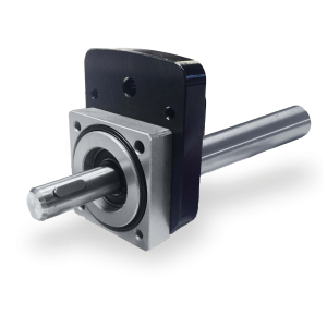
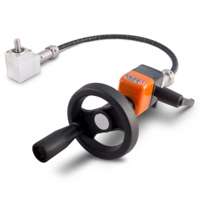
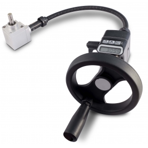
Flanged supports with extension shaft for coupling with position indicators.
➜ for more complete information, see Flanged supports
Richiedi l'accesso
| EFFICIENCY TABLE | ||||
| VERSION | TORSION | MIN. BENDING RADIUS | TORQUE | WEIGHT |
| (°) | mm | Nm | gr | |
| AF6M | 80 | 70 | 3 | 800 |
| AF8M | 70 | 90 | 4.5 | 1100 |
| AF12M | 50 | 160 | 9 | 1600 |
| AF15M | 28 | 300 | 12 | 2100 |
| AF20M | 18 | 400 | 18.5 | 3300 |
|
The data refers to length L=1000mm |
|
MECHANICAL CHARACTERIZATION OF FLEXIBLE SHAFTS |
Flexible shafts are mechanical elements which are subject to torque and undergo a rotational elastic deformation. Considering a single flexible shaft, the equal and opposite torques which are applied at each extremity cause a relative rotation of the various sections which is proportional to the distance between the sections. The relation between Applied Torque T [Nm] and Twist Angle of the extremities φ [°] is a function of three parameters as follows:
● Torsional Rigidity k [103Nm/°] which depends on the section diameter and its construction characteristics
● Length of the shaft L [mm]
● Rotation Direction r (dimensionless parameter which characterizes the asymmetric behavior of the shaft)
| φ = T . L rk |
T = rk . φ L |
Parameter r is equal to 1 when the shaft is loaded according to the winding direction of the spiral; when loaded in the opposite direction, r < 1 as indicated in the following table:
| PARAMETERS OF FLEXIBLE SHAFT | ||||
| Diameter Ø |
k |
r |
Tmax |
Tmax [Nm] φ [°] (L=1000mm, Tmax) |
| 4 | 17 | 0.55 | 1.1 | 64.71 |
| 5 | 26 | 0.55 | 1.8 |
69.23 |
| 6 | 38 | 0.55 | 3.0 | 78.95 |
| 8 | 67 | 0.55 | 4.5 | 67.16 |
| 10 | 101 | 0.55 | 7.5 | 74.26 |
| 12 | 180 | 0.65 | 9.0 | 50.00 |
| 15 | 405 | 0.80 | 12.5 | 30.86 |
| 20 | 1050 | 0.85 | 18.5 | 17.62 |
| BENDING EFFICIENCY |
The above shows a qualitative-quantitative curve of the efficiency of the flexible shaft as a function of the bending radius.
For configurations which are almost in a straight line, the efficiency is equal to the maximum value 0.9.
The efficiency is nearly constant for high values of the bending radius and decreases rapidly down to 0.2 as the minimum bending radius is approached.
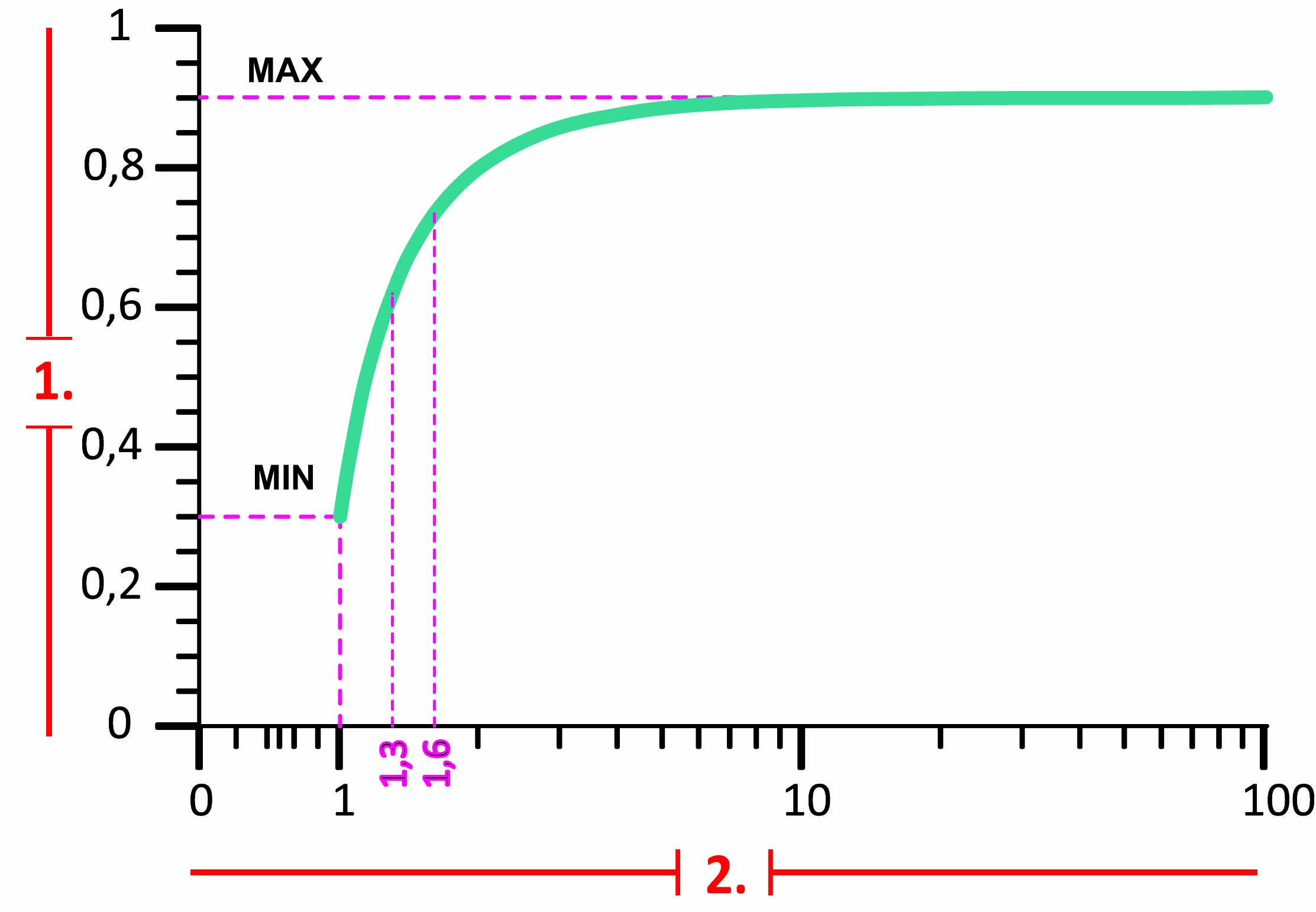
1. Efficiency
2. Bending radius/R min.
| DIAGRAM SHOWING TWIST ANGLE VS TORQUE FOR SHAFTS WITH A TOTAL LENGTH L=1000mm |
| FOR DIAMETERS FROM Ø4 TO Ø10 |
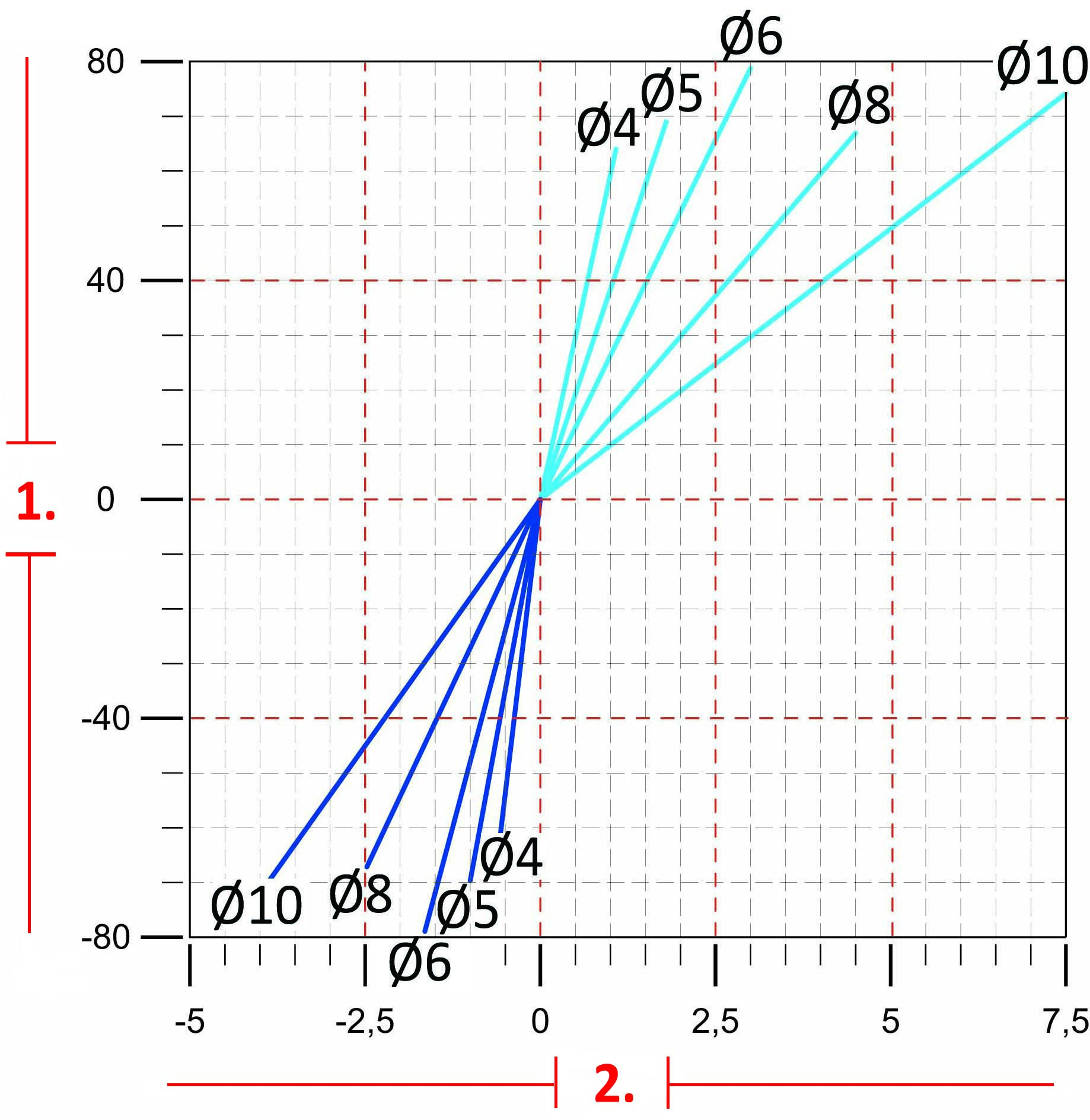
1. Twist angle φ [°]
2. Torque (Nm)
| FOR DIAMETERS FROM Ø12 TO Ø20 |
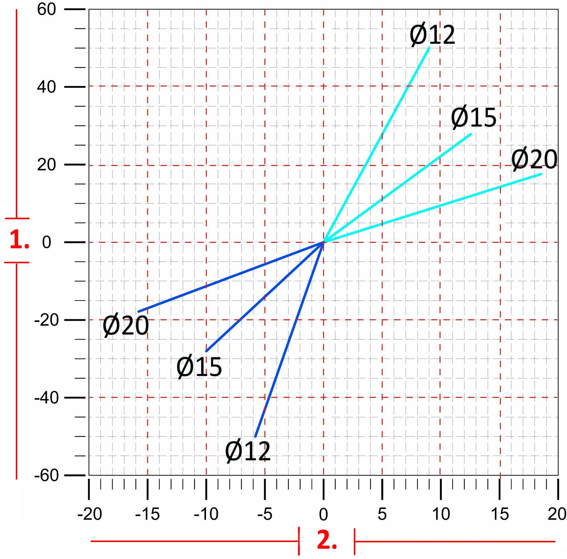
1. Twist angle φ [°]
2. Torque (Nm)
| GENERAL EFFICIENCY TABLE |
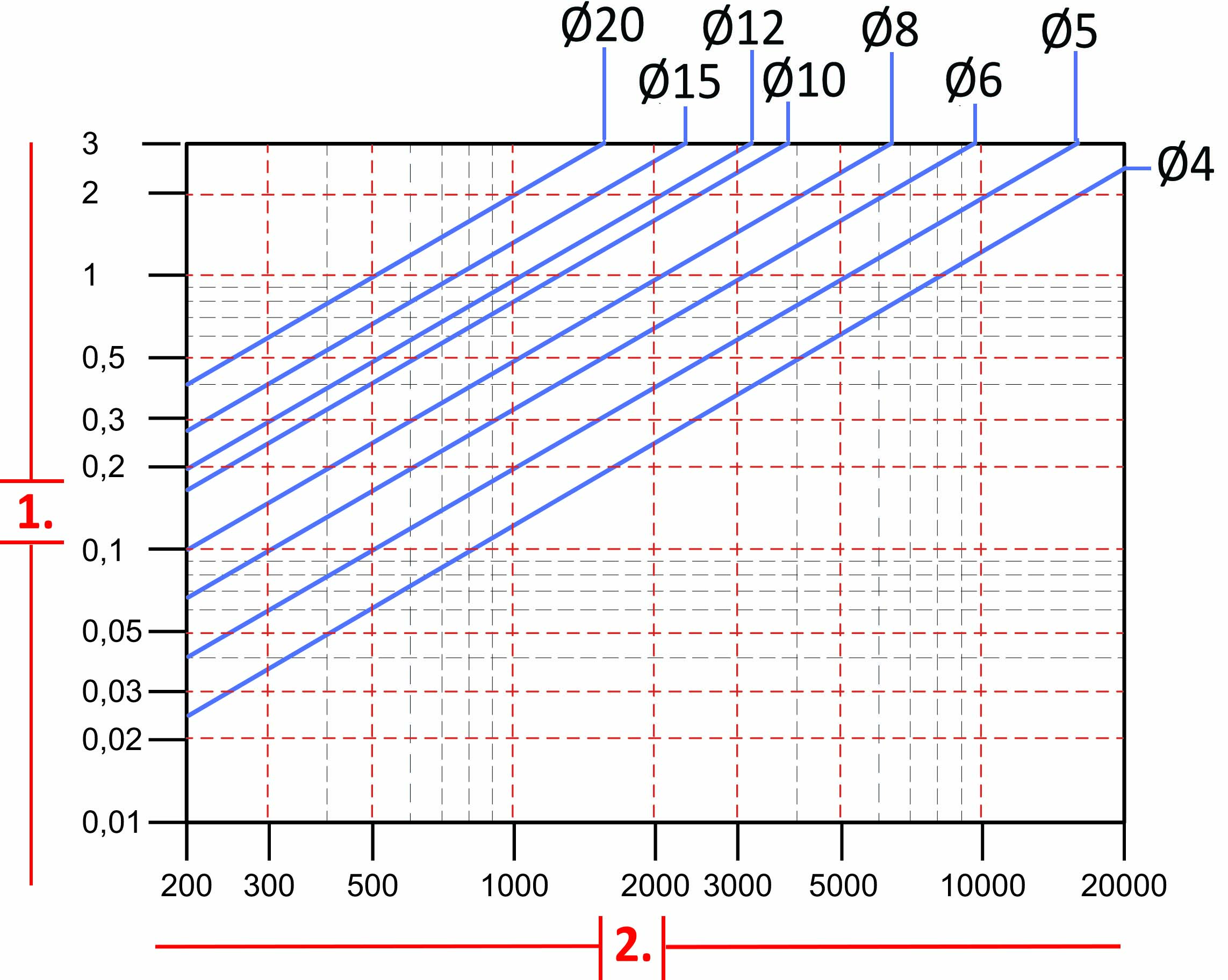
1. Power P (kw)
2. Rotation per minute (rpm)
| - To identify the most suitable flexible shaft for your requirements, refer to the values in the table. If the real loads and efficiency are very close to the table values, contact the technical department. |
| - To choose the most suitable flexibel shaft, we advise to consult the figures, tables, and the technical data shown in the “General Information” of this site. |
| - All tables show linear measurements expressed in <mm>, unless otherwise specified. All forces, efficiency and the loads are expressed in <N or Nm> (10 N ≅ 1 kg or 10Nm ≅ 1Kgm) unless otherwise specified. |


