
MAR50
Screw jacks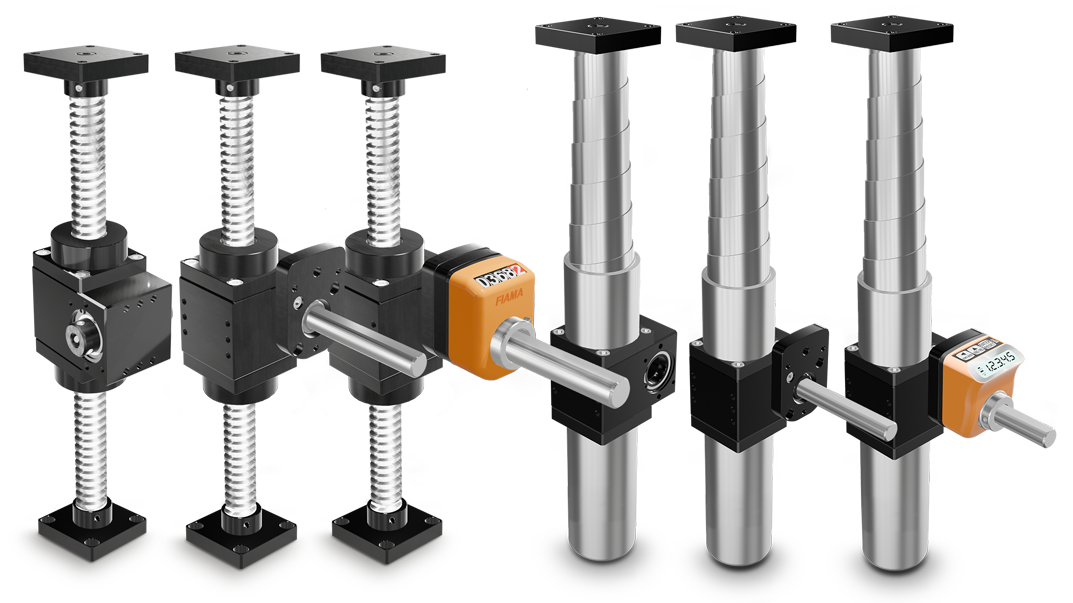
Lifting and actuation systems
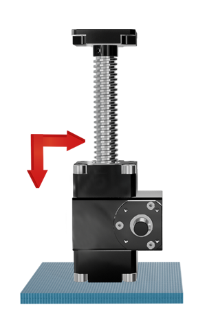
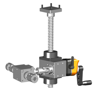
The FIAMA series of screw jacks is a modular mechanical system, for a complete and versatile solution, which transforms rotary movements into linear «push/pull» movements.
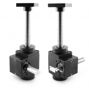
• Trapezoidal screw in AISI 304, stainless steel, TPN Ø18 thread - 4mm pitch
• Case in anodized aluminium, shafts and gears treated with wear-resistant surface hardening
• Trapezoidal screw standard stroke lenghts in mm: 100 - 200 - 300 - 400 - 700 - 1000
• Maintenance-free: lubricated with long-life “Klüber grease
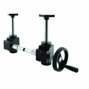
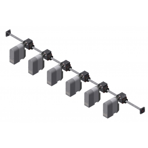
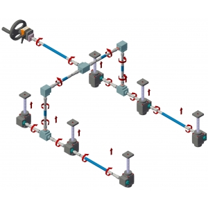
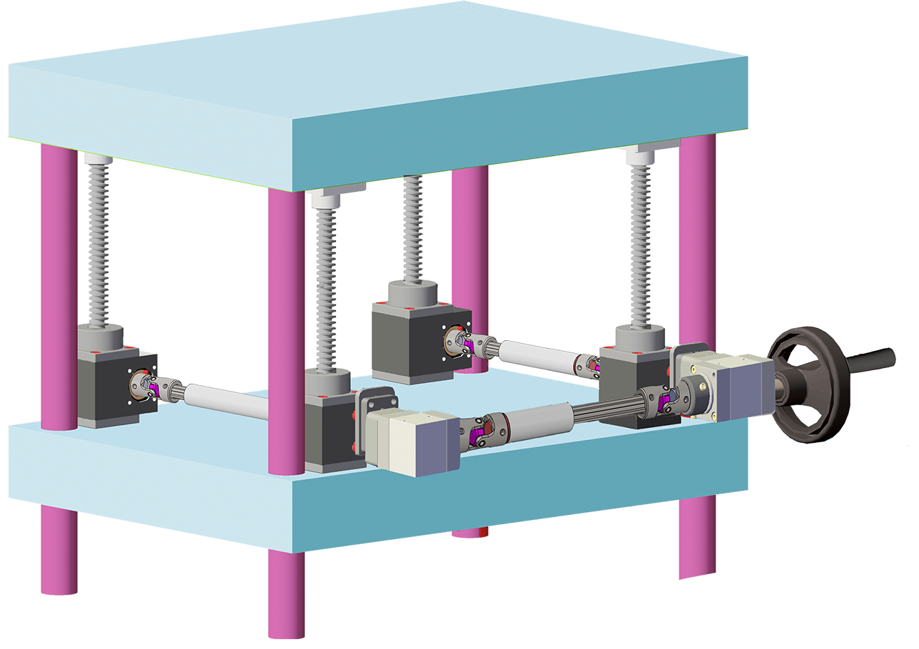
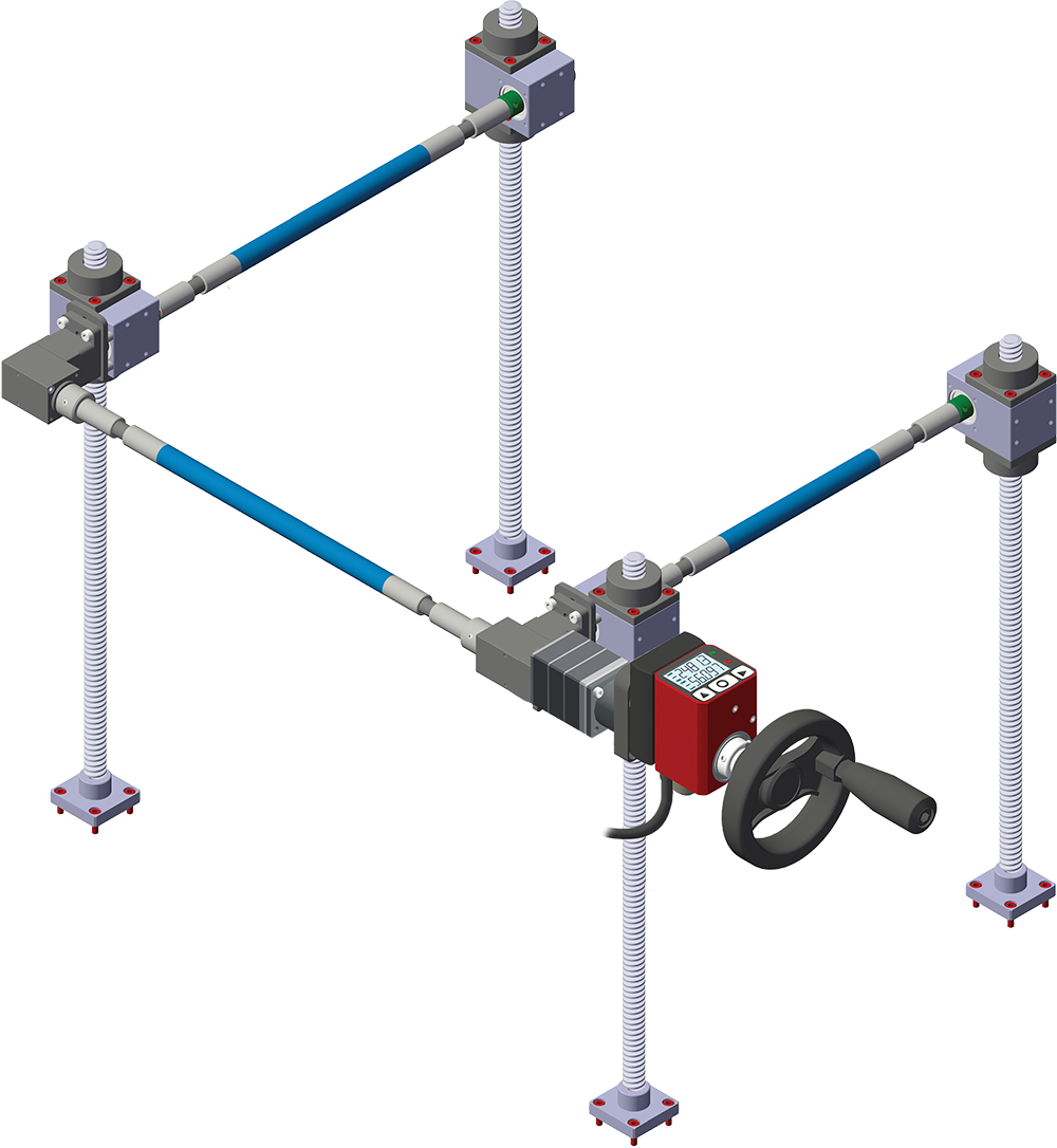
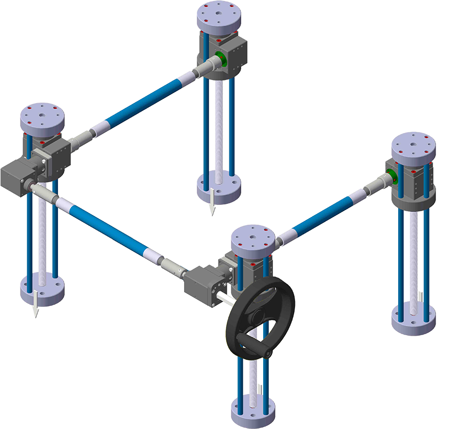
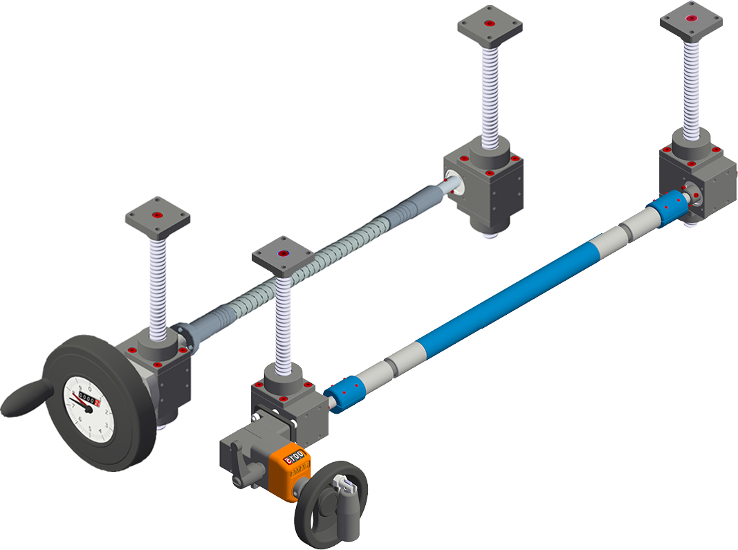
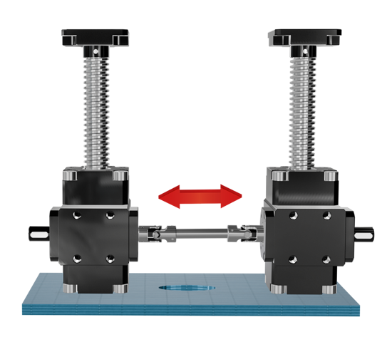
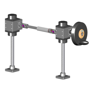
• Can be used individually or combined using flexible shafts, couplings and gearboxes
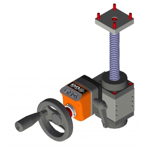
• Manual or motorized motion
Available on request:
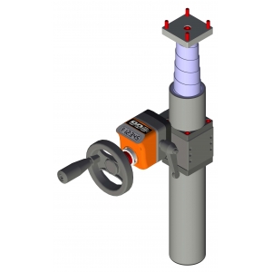
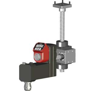
• Supplied complete with fixing flange and extension shaft for display with „OP3“ or „OP7“ digital indicator and„EP3“ or „EP7“ programmable indicator (see dimensions MAR50 FL-OP3/OP7)
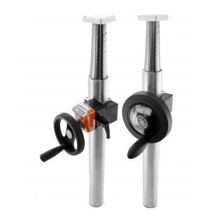
• Rigid protection in aluminium (as option in stainless steel) with stainless steel spiral spring up to 400mm strokes
• In case of continuous use, please contact our Technical Dept. In such applications, a grease fitting will be installed to allow periodic addition of lubricant with a frequency based on the work conditions.
Photogallery


|
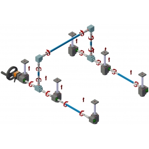
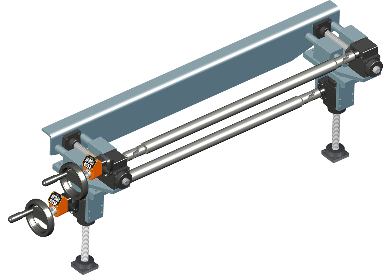
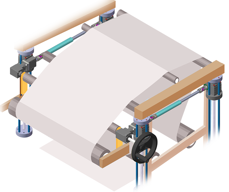
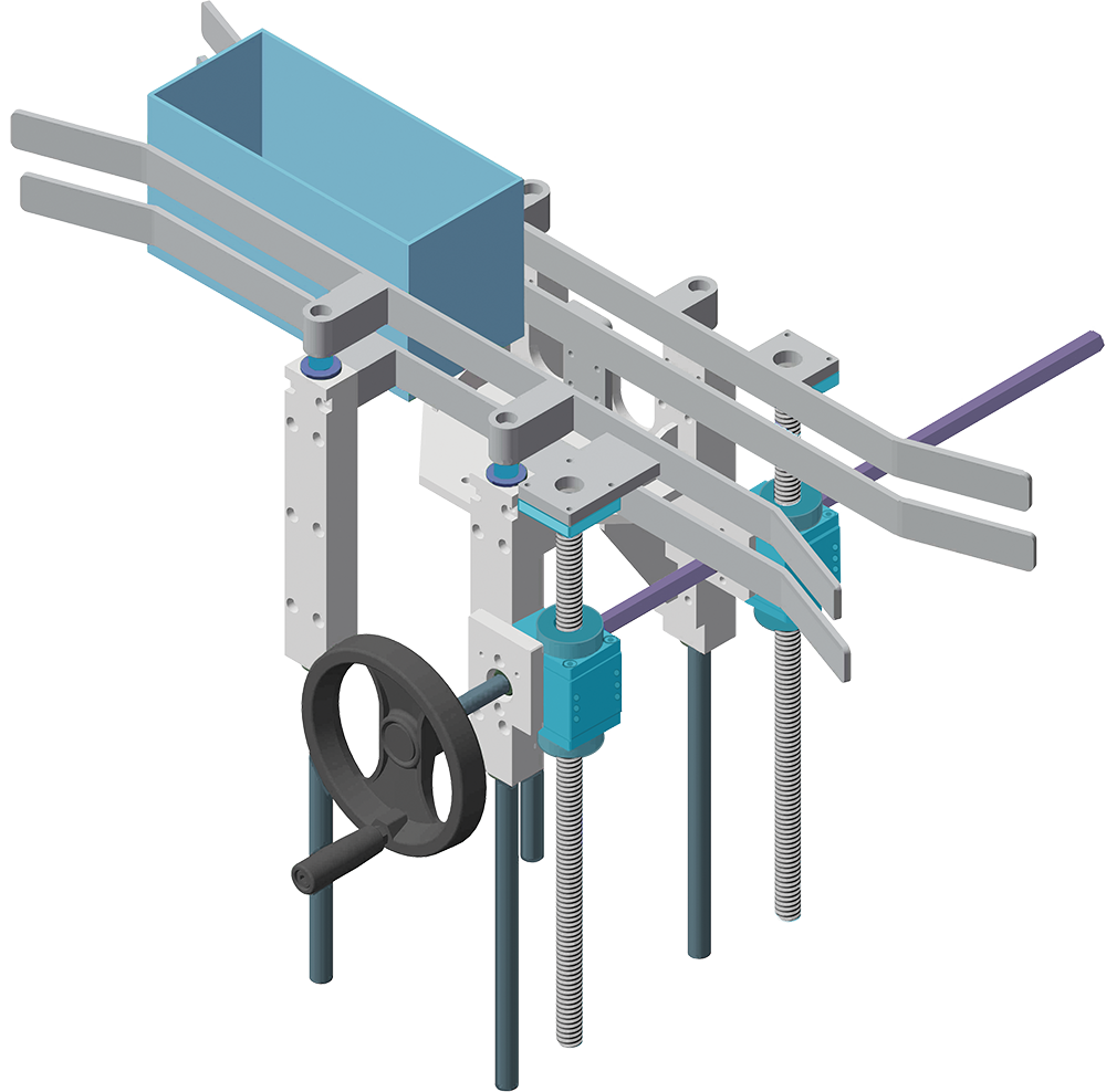
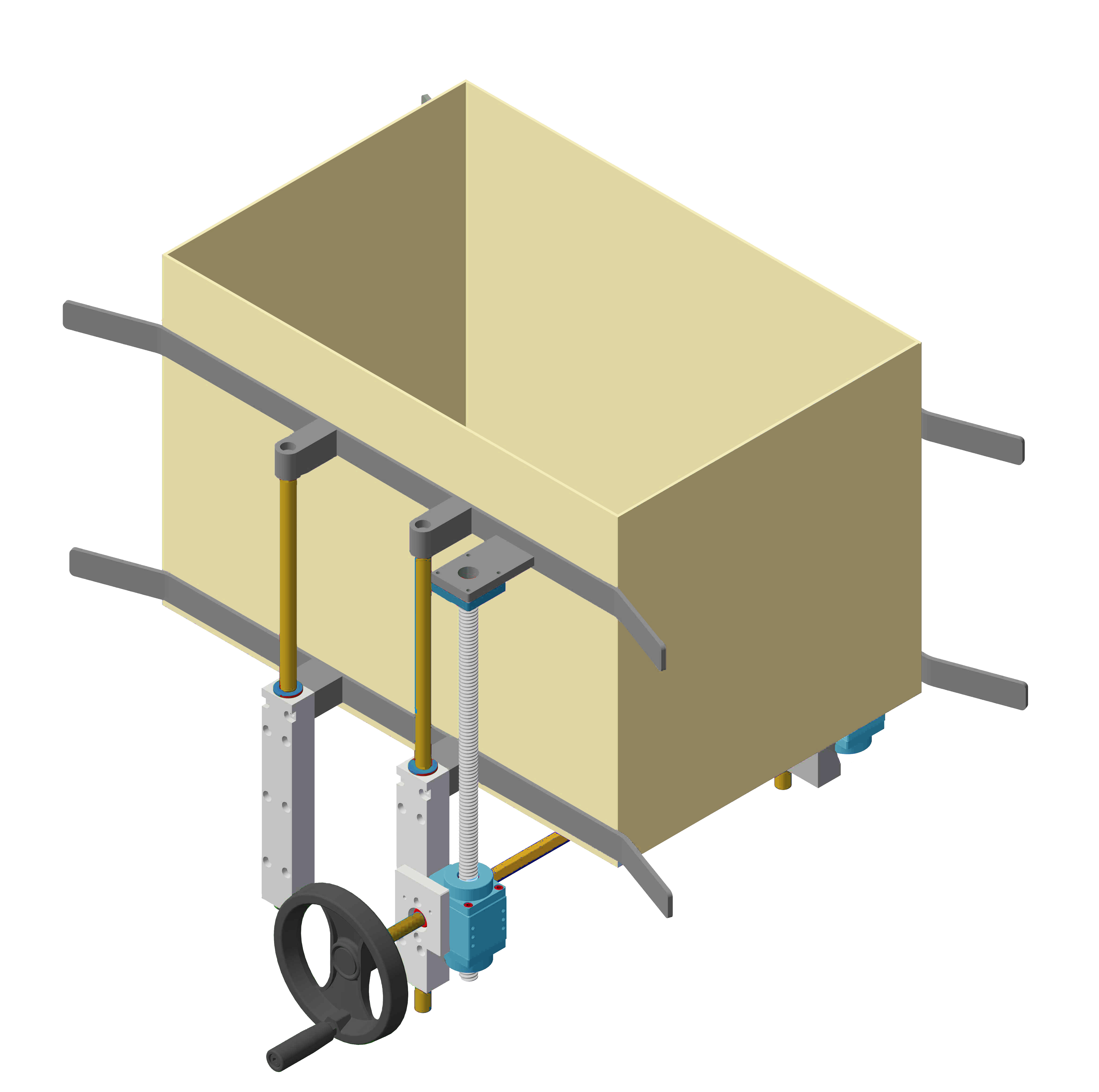
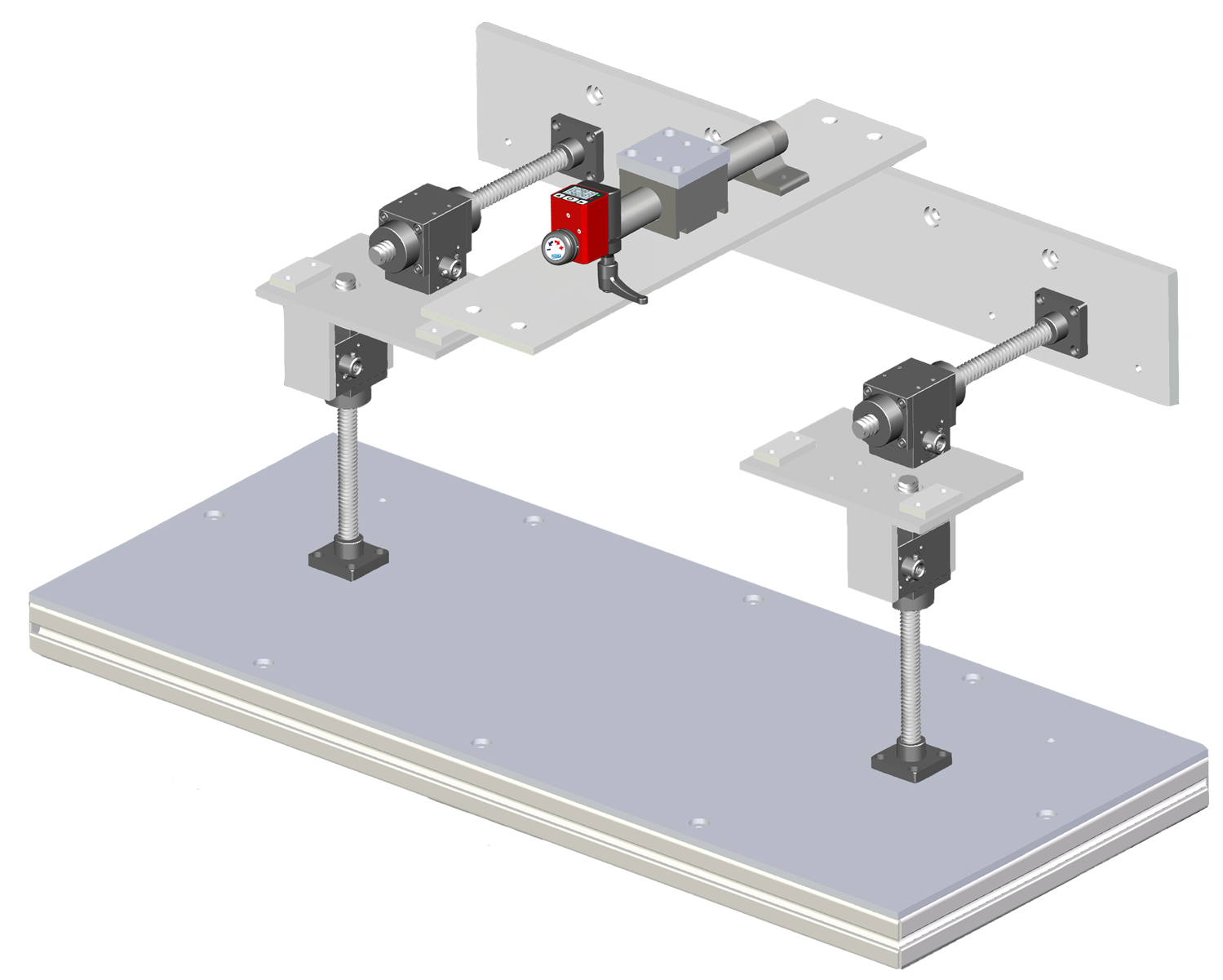
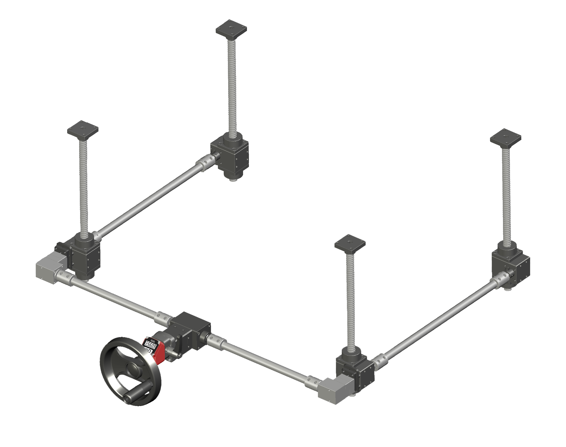
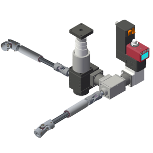
APPLICATION EXAMPLES |
|
 |
|
|
.png) |
 |
 |
 |
 |
 |
 |
 |
 |
 |
 |
 |
 |


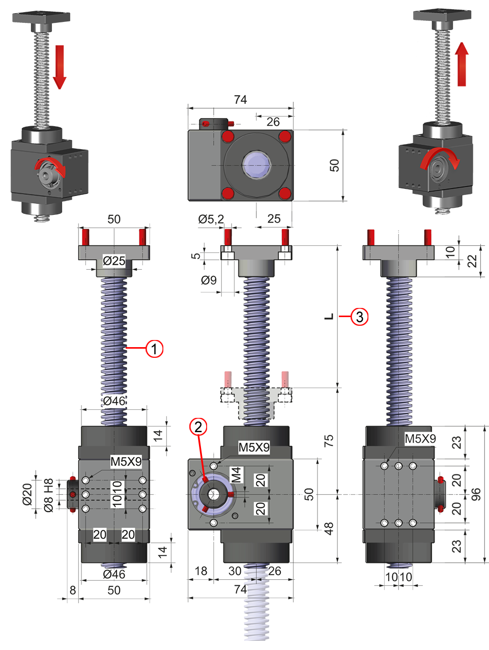
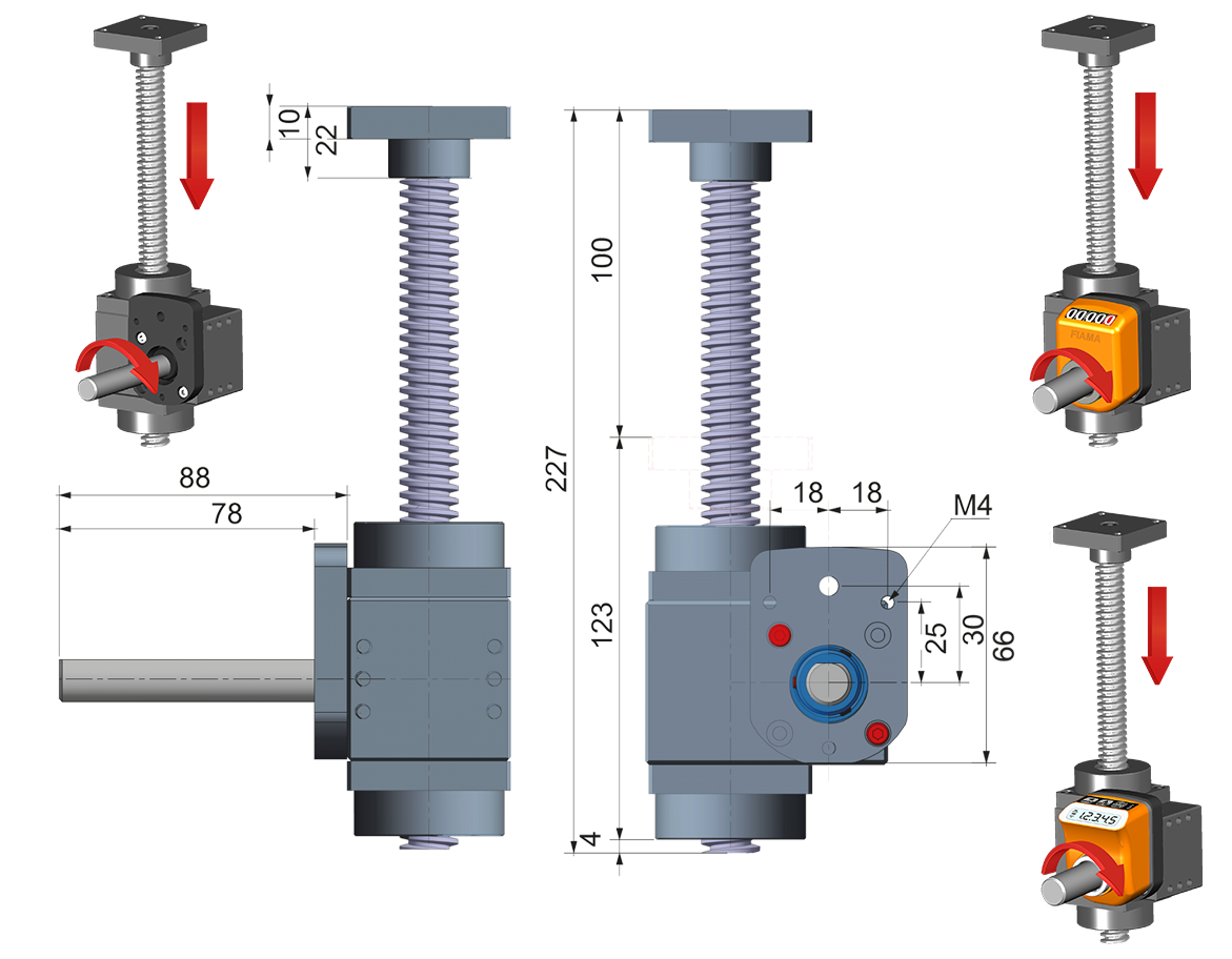
| MAR50 |
 |
|
1. Trapezoidal screw Ø18x4 |
|
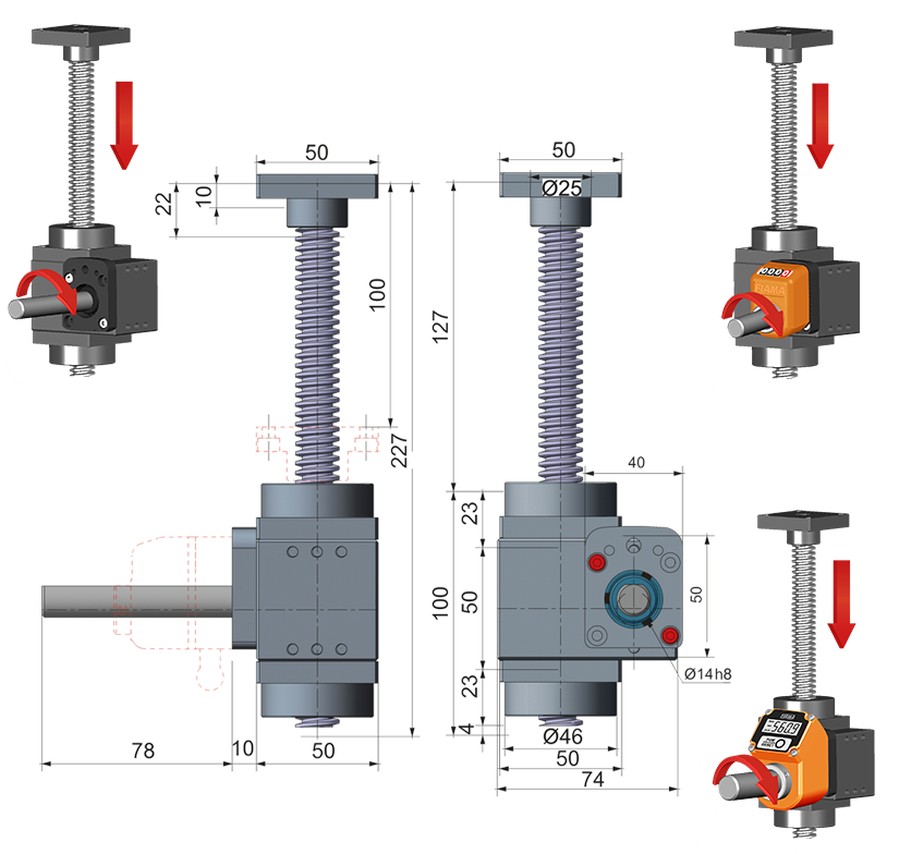
MAR50 FL-OP3/EP3 |
 |
|
MAR50 FL-OP7/EP7 |
 |
|
MAR50-PROT |
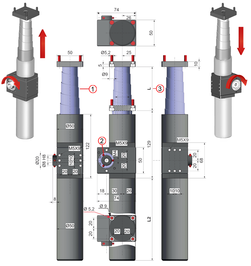 |
| 1. Trapezoidal protection in aluminium & stainless steel spiral spring 2. Nr. 3 fixing screws M4 3. Stroke (mm) |
|
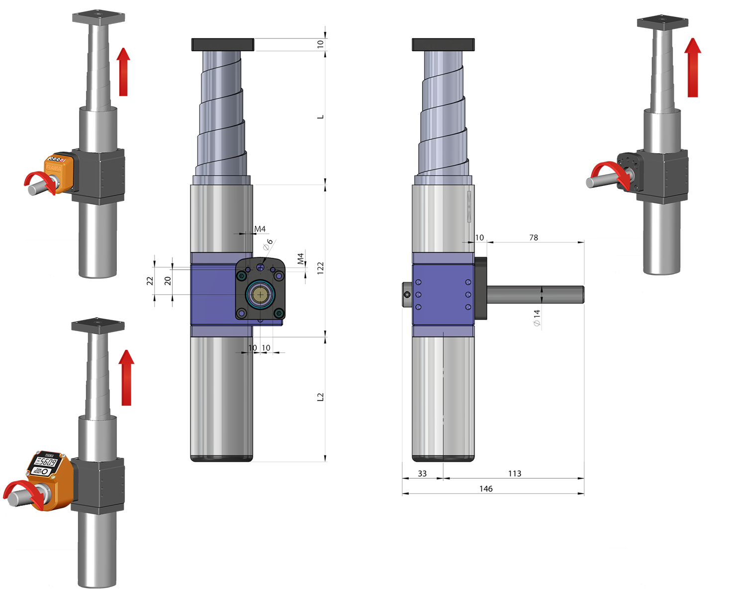
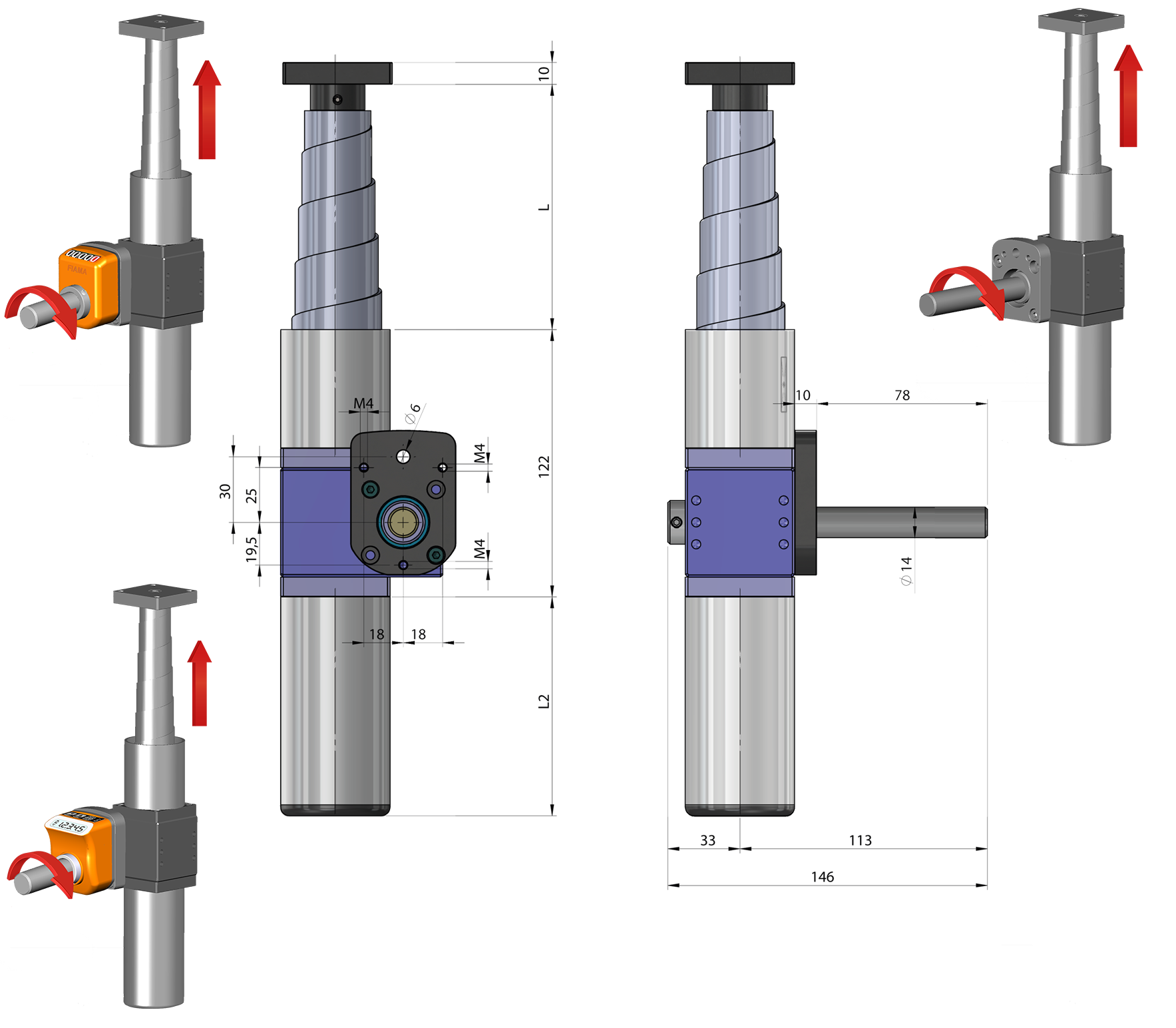
MAR50-PPROT FL-OP3/EP3 |
 |
|
MAR50-PROT FL-OP7/EP7 |
 |
|
SCREW JACK SIZING VERIFICATION |
|
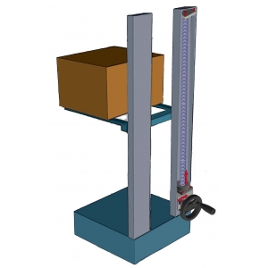
• Load (Kg) = the handled weight which is applied to the threaded bar of the screw jack |
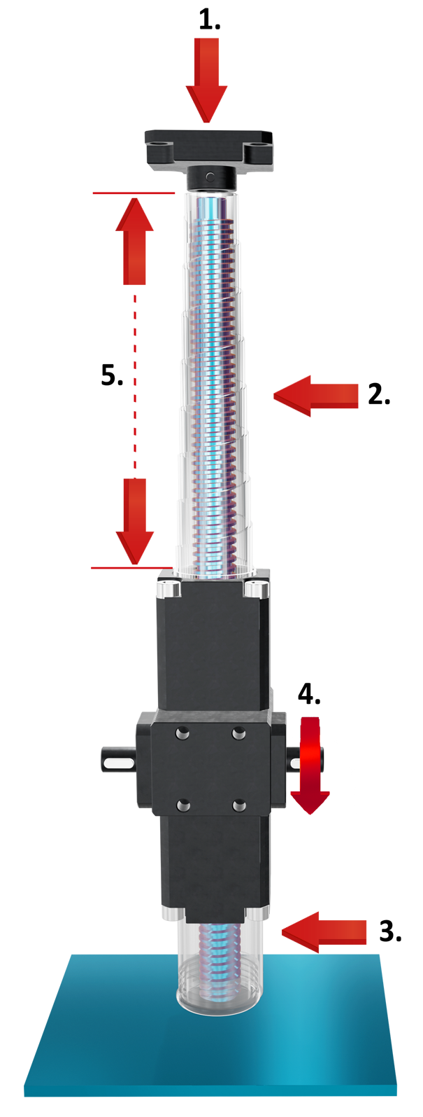 |
| 1. Load (Kg) |
| 2. Upper spiral protection (optional) |
| 3. Lower rigid protection (optional) |
| 4. Rpm (max. 1500) |
| 5. Stroke (mm) |
|
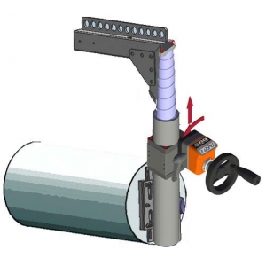
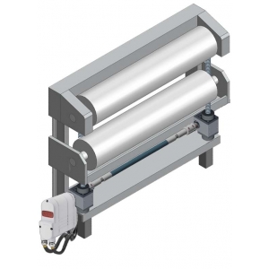
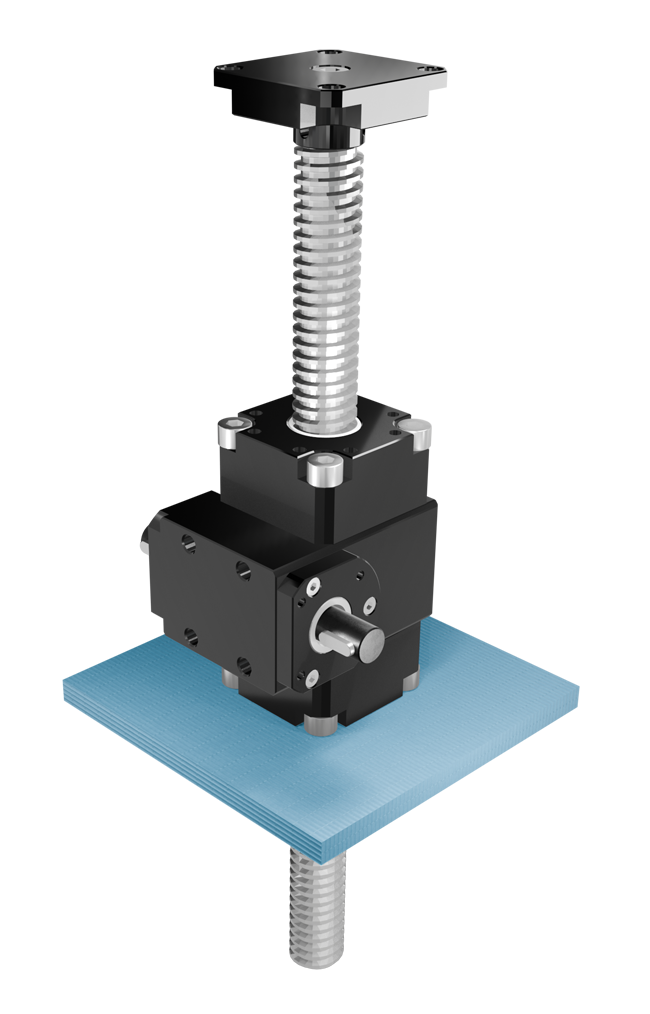
SUPPORT AND MOUNTING |
|
|
Trapezoidal screw jacks require adequate structural support (not included in the supply) to ensure proper load movement and system stability. The unit must be firmly secured to the machine structure using a flat, rigid, and perfectly aligned base. |
|
|
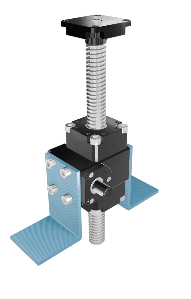
Based on the application configuration: |
|
 |
 |
|
Bottom support: plate/bracket under housing for optimal mounting. |
Side support: allows a maximum load of 200 kg. |
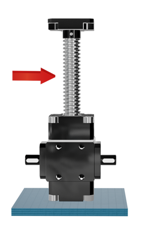
| INSTALLATION | |
 |
 |
|
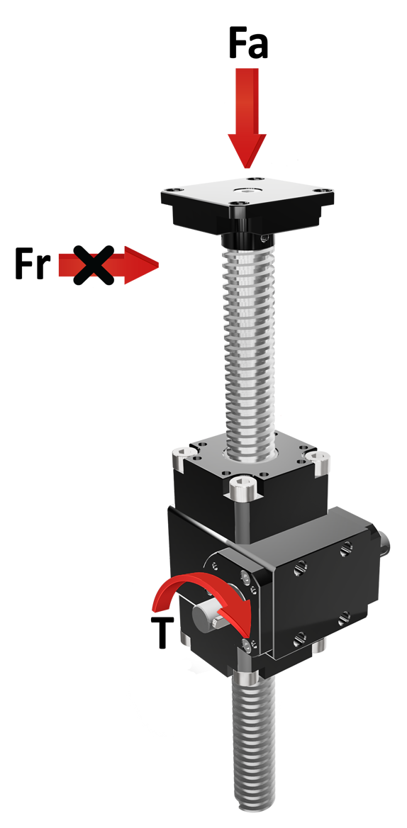
Installation must not create radial/lateral loads, which are the main cause of failure, on the threaded bar. |
The plane to which the screw jack is fixed and the threaded bar must be orthogonal and the load and the bar must be coaxial avoiding eccentricity. |
 |
|
|
When applying multiple screw jacks (connected also by transmissions) the terminals must be perfectly aligned so that the load is uniformly distributed; in this case it is recommendable to use couplings to compensate misalignments. |
|
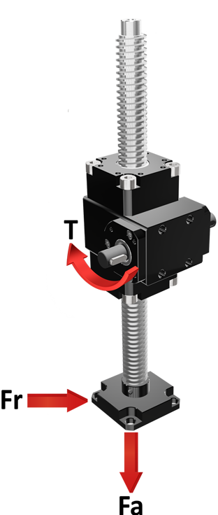
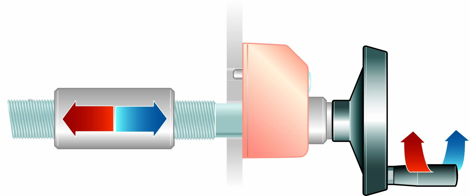
| REPRESENTATION OF LOADS |
|
The loads acting on shafts, with reference to the shaft axis, can be radial (Fr) or axial (Fa). For screw jacks, the loads can be in tension or compression (to be specified when ordering). Fr = radial force/load, acting perpendicular to the shaft/axis Note: the maximum allowable values of Fr, Fa, and T depend on the model and operating conditions. |
|
Pull |
Push |
 |
|
|
Calculation applied to all models |
| THEORETIC EXPECTED LIFE✽ = 10.000H X Fu
|
✽ The lifetime of 10.000h considers the following conditions:
• Applied torque = advised torque (see tables)
• Maximum of 8 working hours per day
• Working temperature 20 °
• No shocks
• Ta Output torque actually applied
• Max torque applied (see tables/models)
|
GLOSSARY |
|
FR = radial force |
|
FA = axial force |
| R = efficiency |
| T = torque |
| Tm = maximum torque |
| Tr = recommended torque |
| Ta = applied torque |
| To = output torque |
| Ti = input torque |
| Pn = power |
| N = Newton |
| Nm = Newton meter |
| fu = use coefficient |
| i = transmission ratio |
| rpm = revolutions per minute (1/min) |
| n1 = input shaft |
| n2 = output shaft |
| M = protruding / male shaft |
| F = blind hollow shaft / female |
| F = through hollow shaft / female |
| ⦿ For correct sizing is necessary to know: transmitted power (Pn), output torque (T) andinput rotation speed (rpm). |
|
⦿ To identify the most suitable gearbox for your requirements, refer to the values in the table. If the real loads and efficiency are very close to the table values, contact the technical department. |
|
⦿ All tables show linear measurements expressed in <mm>, unless otherwise specified. All the reduction ratios are expressed as a <fraction> unless otherwise specified. All forces are expressed in N, loads in kg, torques in Nm, and efficiencies in %, unless otherwise specified. |


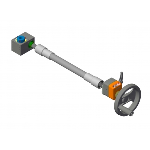
Control handwheel with folding handle, thermoplastic material, steel bush.
➜ for more complete information, see V.R

Crank handle with folding handle in thermoplastic material, steel bush.
➜ for more complete information, see V.M

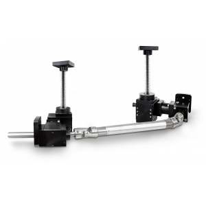
Flanged supports with extension shaft for coupling with position indicators.
➜ for more complete information, see Flanged supports
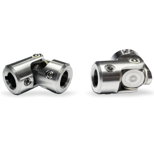
The «GC» and «GCC» cardan joints used for the transmission of torque and movement of non-aligned elements.
Main features: universal application, high reliability, maintenance free, extremely precise and ease-of-use.
• Case entirely machined from solid, in stainless steel AISI303.
• Suitable for intermittent (UI) and continuous movements (UC).
• Maximum working angle 45 °.
➜ for more complete information, see GC and GCC

• The telescopic shafts are ideal to connect two elements with a constant or variable center to center distance.
• Suitable for adjustments and for continuous use.
• Torque from 5 Nm to 10 Nm.
➜ for more complete information, see ATE

• The telescopic shafts are ideal to connect two elements with a constant or variable center to center distance.
• Suitable for adjustments and for continuous use.
• Torque from 25 Nm to 50 Nm.
➜ for more complete information, see ATS

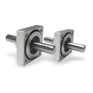
The AR series of rigid shafts is used to directly connect parts which are perfectly aligned without any offset.
The main advantages are universal applicability and high reliability.
• Suitable for use in manual and motorized motion transfer.
• Simple and quick installation without additional supports.
➜ for more complete information, see AR


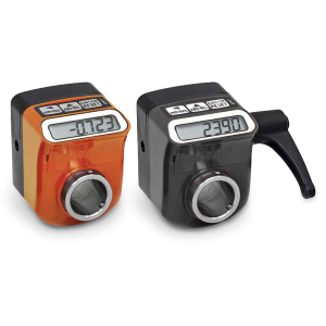
• 4 digits counter (standard red digit indicates decimals; on request 2 red digits for hundredths or 4 black digits for mm). Reading until 9999.Digit height 5 mm
• Standard shaft bore: ø14H7; other bores, smaller than 14 with reducing bush.
➜ for more complete information, see OP3

• 5 digits counter (standard red digit indicates decimals; on request 2 red digits for hundredths or 5 black digits for mm).
• Readings until 99999. ‘Lens to improve the reading’: digit height 7 mm.
• Standard shaft bore ø20 (OP7) or ø25 bore (OP7F25). Other holes smaller than 20 with reducing bush.
➜ for more complete information, see OP7
• Measures linear or angular movements, applicable to many types of industrial
• Simple assembly through the hollow shaft
• Powered by long battery life, easy replacement from the front
➜ for more complete information, see EP7

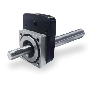
Angular gearbox 66/5 with flange MØ14x68 FL-OP3/EP3 and MØ14x80 FL-OP7/EP7, designed for connection with the position indicator. It ensures precise adjustments and accurate monitoring of the position, enhancing stability and reading accuracy. The flange, made of black anodized aluminum, perfectly matches the gearbox case, both featuring the same elegant and durable finish.
➜ for more complete information, see 66/5

The EP3 electronic indicator allows monitoring of adjustments to eliminate errors and a precise reading of linear or angular displacements.
• 100% interchangeable with mechinal indicator OP3.
• Powered by a long-life battery, easy replacement from the front.
• Hollow shaft made of stainless steel; shock, vibration and dirt resistant plastic case.
➜ for more complete information, see EP3

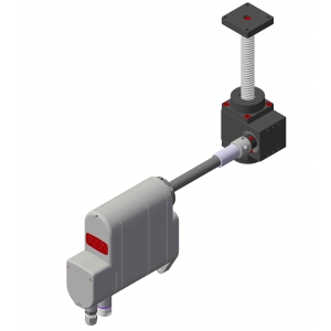
● Drive and position control integrated into a single device.
● Ultracompact design for simple installation; ø14mm output shaft with 5mm flat key.
● Communication protocols: Profinet, Ethernet/IP, Powerlink, EtherCAT.
➜ for more complete information, see SERVO.ALL

The Servo-OP is an electric rotary actuator which, in combination with the optional OP3 indicator, allows position control with two buttons.
• Compact case made of anodized aluminum
• Hollow shaft output
➜ for more complete information, see SERVO.OP
Photogallery


Richiedi l'accesso
|
LEGEND FOR PERFORMANCE TABLES |
||
|
Tab. 1 |
= |
moving loads as to input torque |
|
Tab. 2 |
= |
moving loads as to trapeziodal screw (with use of guides) |
|
Tab. 3 |
= |
screw travel speed according to revolution nr. |
|
i |
= |
reduction ratio [/] |
|
T |
= |
torque [Nm] |
|
C |
= |
moving load [kg] |
|
s |
= |
stroke [mm] |
|
ω |
= |
rotation speed [rpm] |
|
v |
= |
travel speed [mm/s] |


