
RINV-OP64
Flanged gearboxes
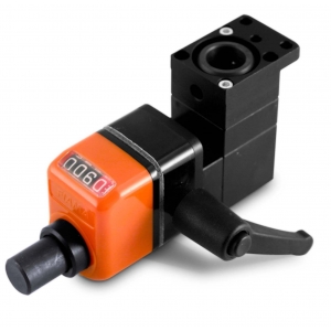
The RINV-OP64 is a flanged angular transmission that, combined with a position indicator type “OP”, allows to carry out a visualized adjustment, angular or linear, even if the shaft is in an uncomfortable position.
• Several visualizations and connections possibilities.
• Available with reduction ratios : 1:1 - 1:2.
• Maximum output torque 6 Nm.
• Aluminium case, anodised. Steel shafts. Steel bevel gears, case-hardened.
• Minimum angular backlash, minimum axial backlash.
• Movements on ball-bearings, water-proof.
• Radial load 15 kg - axial load 1,5 kg
• Weigth gr. 300.
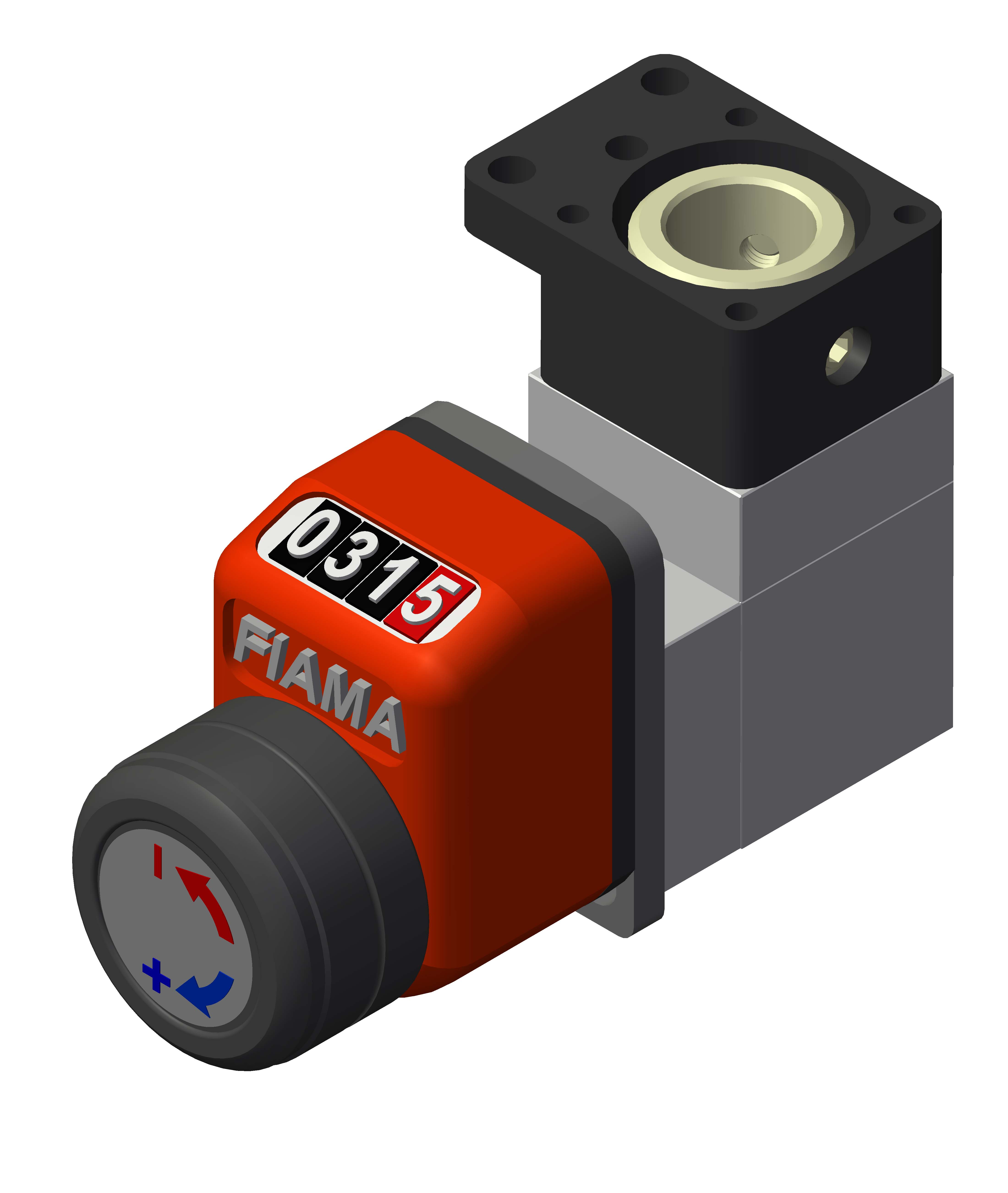
Photogallery


| RINV-OP64 |
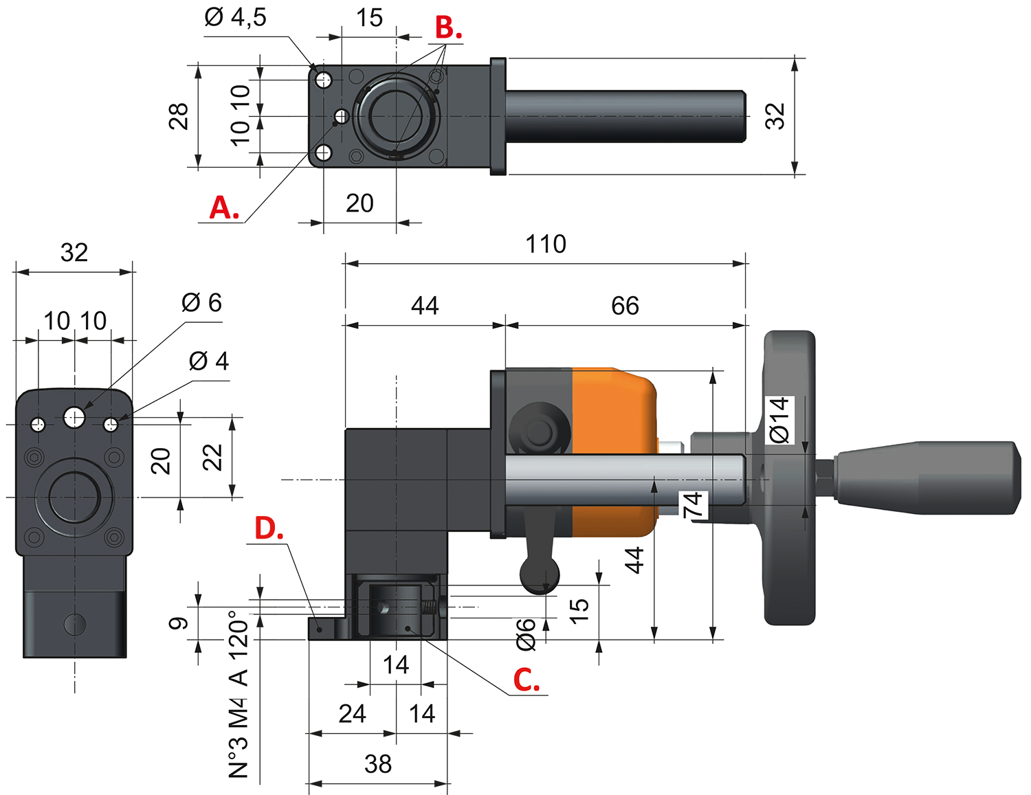 |
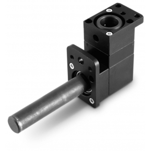
| A. Antirotation bore Ø4 |
| B. 3 screws M4 at 120° |
| C. Hollow shaft Ø14x15 |
| D. Fixing flange for gearbox |
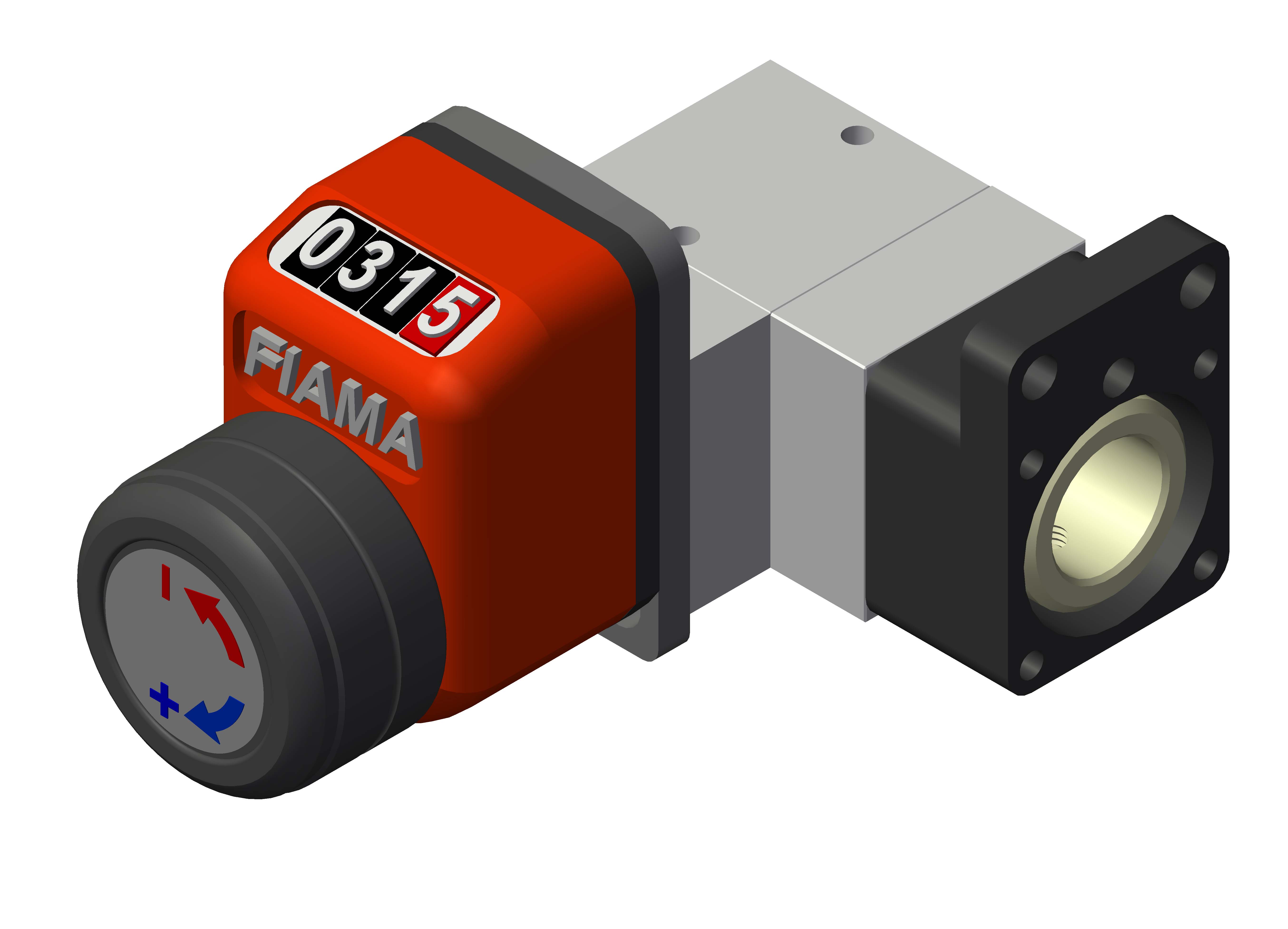
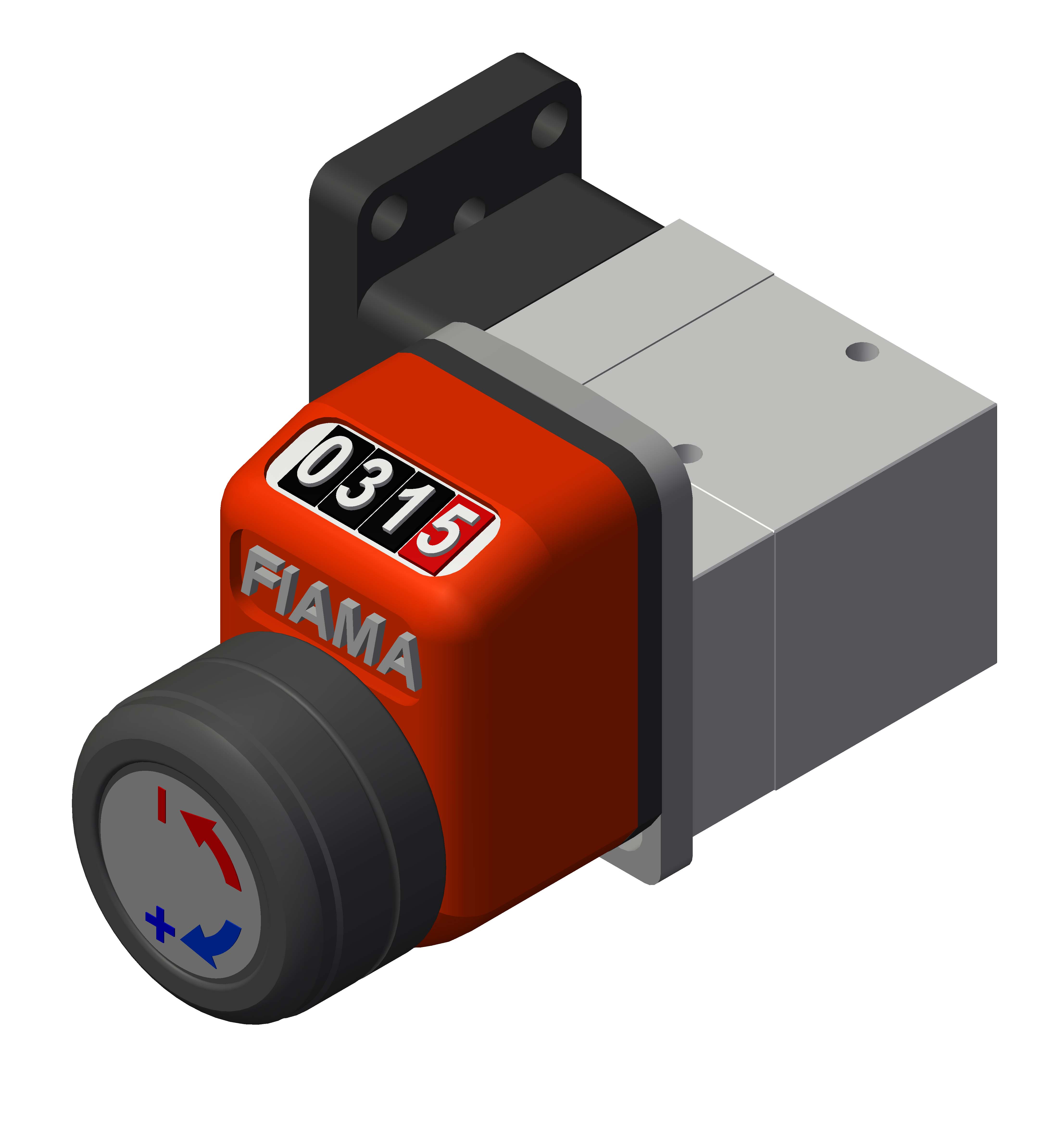
| EXAMPLES OF MOUNTING POSITIONS | |||
 |
 |
||
 |
 |
||
| The RINV-OP is supplied standard as per overall drawing. To change the mounting position of the two flanges (flange OP and fixing flange RINV-OP), screw-off the two fixing screws, turn the flange in desired position, and fix the two screws. Insert the machine shaft Ø14 into the hollow shaft of the RINV-OP, the anti-rotation lock-pin Ø4 on the fix part of the machine then lock the fixing screws M4 through the bore of the flange. |
|||


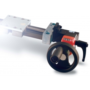
Control handwheel with folding handle, thermoplastic material, steel bush.
➜ for more complete information, see V.R

Crank handle with folding handle in thermoplastic material, steel bush.
➜ for more complete information, see V.M

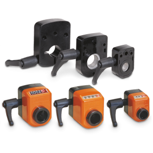
With the shaft block flange on the OP2, OP3, OP6, OP7, OP5, OP9 indicator as a compact unity, we obtain a safe blocking of the drive shaft.
➜ for more complete information, see FL-B


• 4 digits counter (standard red digit indicates decimals; on request 2 red digits for hundredths or 4 black digits for mm). Reading until 9999.Digit height 5 mm
• Standard shaft bore: ø14H7; other bores, smaller than 14 with reducing bush.
➜ for more complete information, see OP3
Photogallery


Richiedi l'accesso
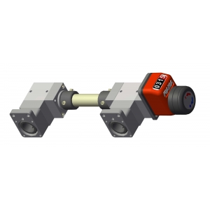
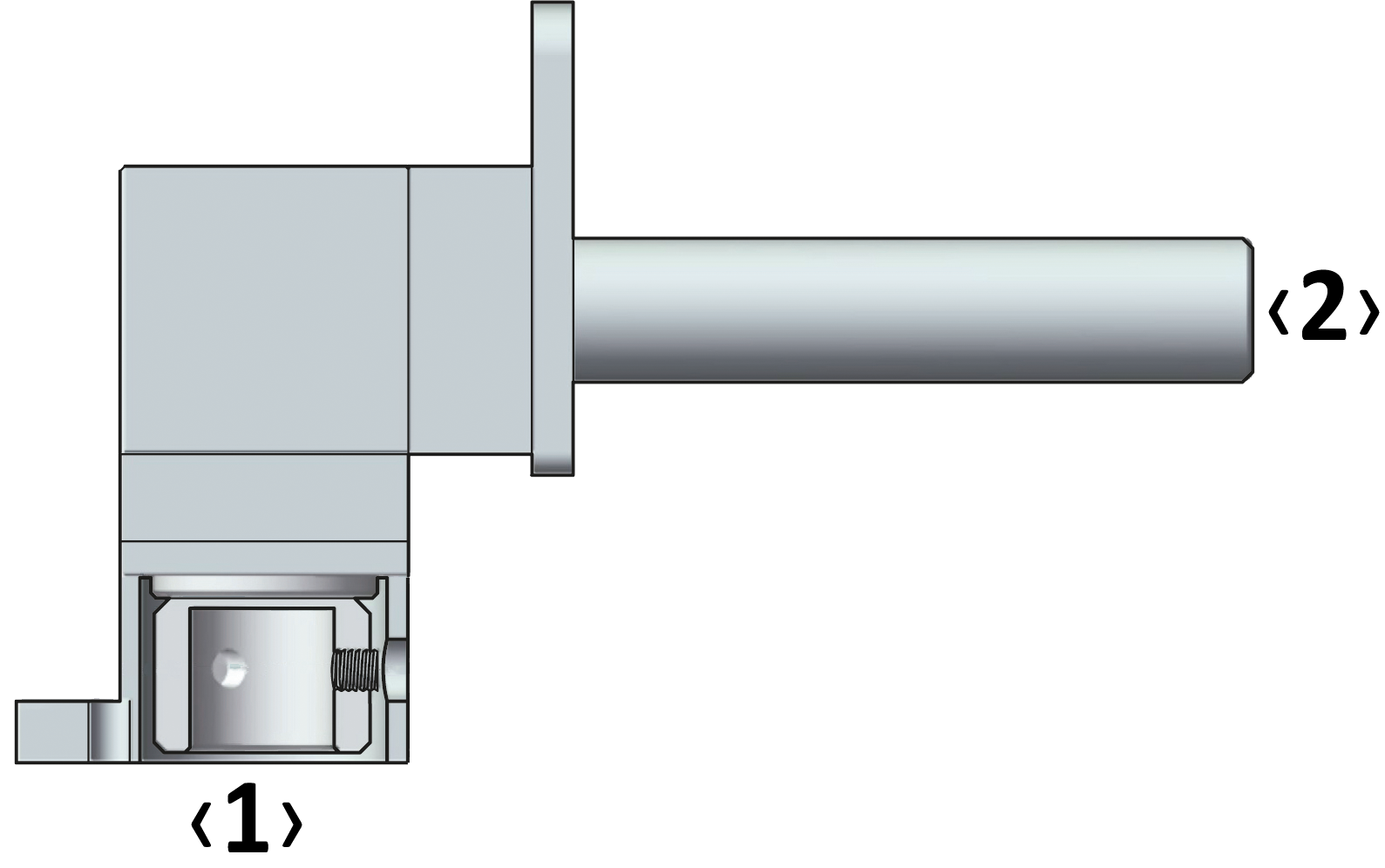
| REPRESENTATION OF REDUCTION & MULTIPLYING RATIO | ||||
| Example | ||||
|
ratio 1:2 ---------------------------------- |
 |
|||
|
‹1› = machine side |
||||
|
The ratio is determined by the shaft ‹1›. |
||||
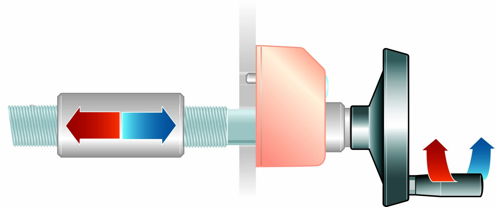
| RADIAL AND AXIAL LOAD | ||
| Fig. 8 | ||
 |
Fr = max 150 N radial load, is the load acting in perpendicular direction to the shaft/axise | |
|
Fa = max 15 N axial load, is the load acting of the shaft/axis |
||
| T = 4 Nm output torque | ||
|
The loads acting on the shafts can be of two types, referred to the axis of the shaft (Fig. 8): : |
| OUTPUT TORQUE WITH RATIO 1/1 |

| Efficiency = 90% |
| OUTPUT TORQUE WITH RATIO 1/2 |

| Efficiency = 90% |
| OUTPUT TORQUE WITH RATIO 2/1 |

| Efficiency = 90% |


