




66/4UC
Continuous use gearbox
|
• Ideal for continuous motorized use at maximum efficiency, without any loss of power. |
||
|
• The component configuration ensures handling of constant loads with smooth, and uninterrupted operation. |
||
|
• Oil bath lubrication for speeds above 200 rpm; grease lubrication for speeds below 200 rpm. |
||
|
• Available transmission ratios: 1:1 - 1:2 - 2:1 ( available in versions «A» - «B» - «C»). |
||
|
• Aluminium case, anodised; AISI 303 stainless steel shafts (standard). |
||
|
• Max. transmissibile torque 8 Nm. |
||
|
• Models: |
||
|
- Version «A» with 2 outputs; weight 270 g. |
||
|
- Version «B» with 3 outputs; weight 290 g. |
||
|
- Version «C» (opposite rotation) with 3 ouputs; weight 310 g. |
||
|
- Version «D» with 3 outputs, 2 through hollow shafts; weight 260 g. |
||
|
• Standard shafts: M = male Ø8CH2 / F = female Ø8CH2 (Tab. 9). |
||
|
Available on request: |
|
|
|
▪ Shafts: M = male Ø10CH3 - Ø14CH5. |
||
|
▪ Shafts: F = female Ø10CH3 - Ø14CH5. |
||
|
▪ Custom configurations |
Photogallery

|
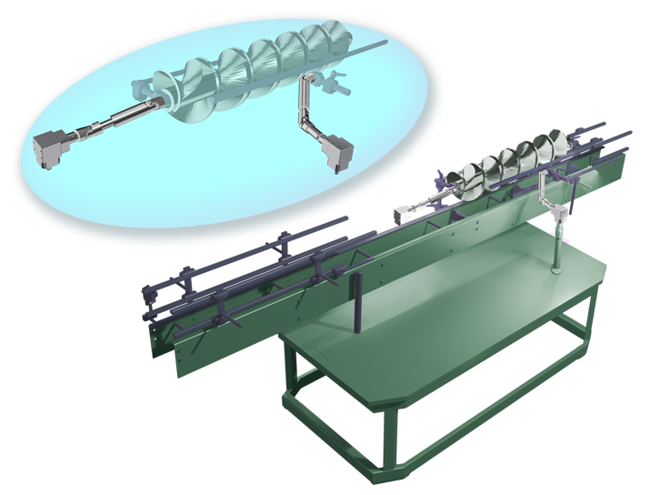
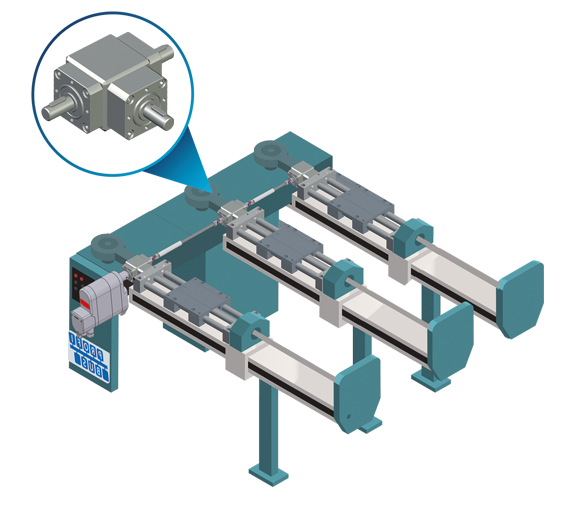
APPLICATION EXAMPLES |




| VERSION WITH DIMENSION DRAWINGS | |||||||
|
|||||||
| Version «A» M-M | |||||||
-F(Ø8).png) |
|||||||
| Version «A» M-F | |||||||
-F(Ø8).png) |
|||||||
| Version «A» F-M | |||||||
-M(Ø8).png) |
|||||||
| Version «A» F-F | |||||||
-F(Ø8)_1.png) |
|||||||
| Version «B» M-M-M | |||||||
-M(Ø8)-M(Ø8).png) |
|||||||
| Version «B» F-M-M | |||||||
-M(Ø8)-M(Ø8).png) |
|||||||
| Version «C» M-M-M | |||||||
-M(Ø8)-M(Ø8).png) |
|||||||
| Version «C» M-F-F | |||||||
-F(Ø8)-F(Ø8).png) |
|||||||
| Version «C» F-M-M | |||||||
-M(Ø8)-M(Ø8).png) |
|||||||
| Version «C» F-F-F | |||||||
-F(Ø8)-F(Ø8).png) |
|||||||
| Version «D» F-F-F | |||||||
-F(Ø8)-F(Ø8).png) |
|||||||
| Version «D» M-F-F | |||||||
-F(Ø8)-F(Ø8).png) |


|
CONFIGURATION AND DIRECTION OF ROTATION |
Tab.1 |
||
| AVAILABLE VERSIONS | |
| ⟪A⟫ | ⟪B⟫ |
|
|
 |
|
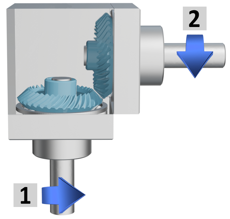
2 outputs, same rotation direction |
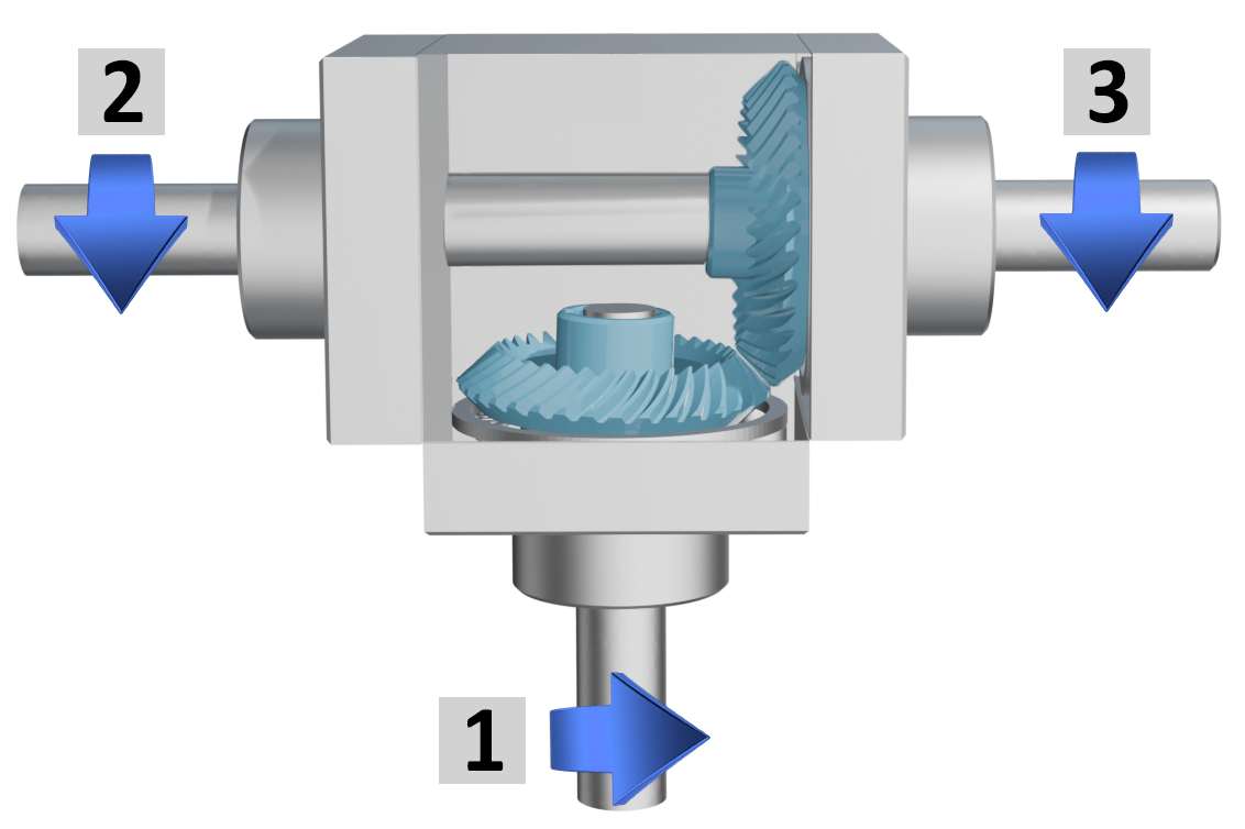
3 outputs, same rotation direction |
| ⟪C⟫ | ⟪D⟫ |
|
|
|
|
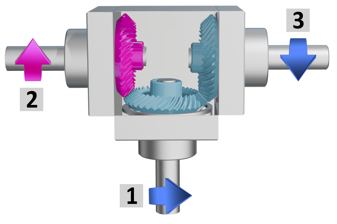
3 outputs, 1 with opposite rotation directions |
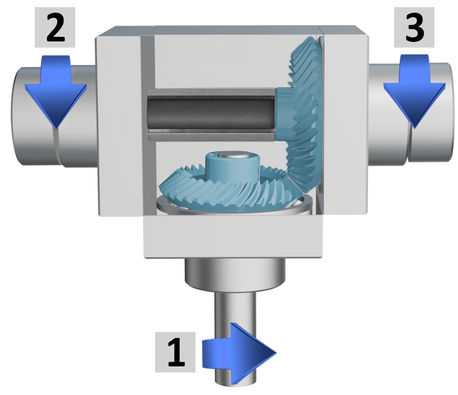
3 outputs, 2 with through hollow shafts, same rotation direction |
|
|
|
|
OUTPUT SHAFT IDENTIFICATION |
Tab.2 |
| AVAILABLE OUTPUT SHAFTS | ||||||||
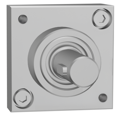
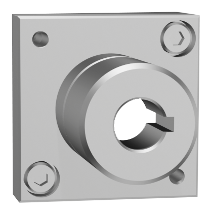
| male = M |
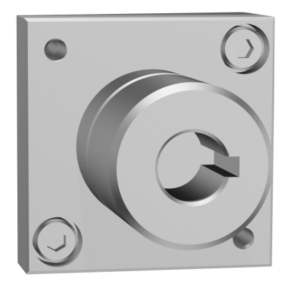
female blind = F |
through female = F |
||||||
 |
 |
 |
||||||
|
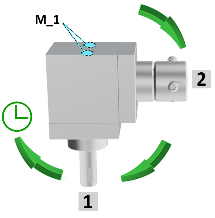
Example with 2 outputs |
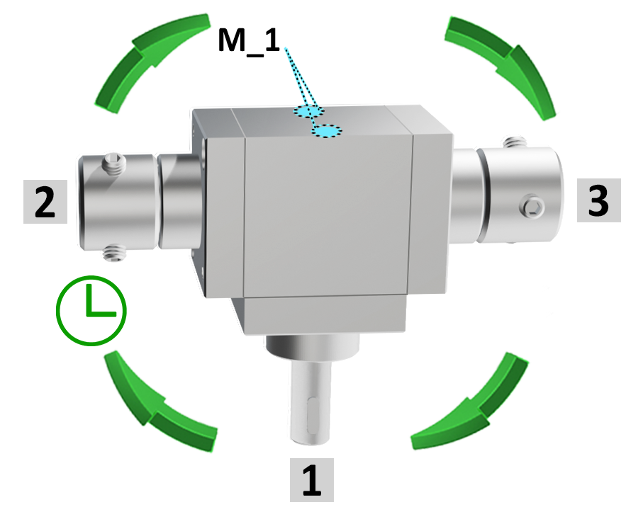
Example with 3 outputs |
 |
 |
|
|
|
|
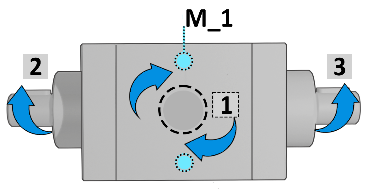
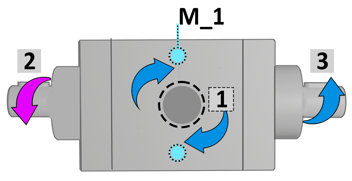
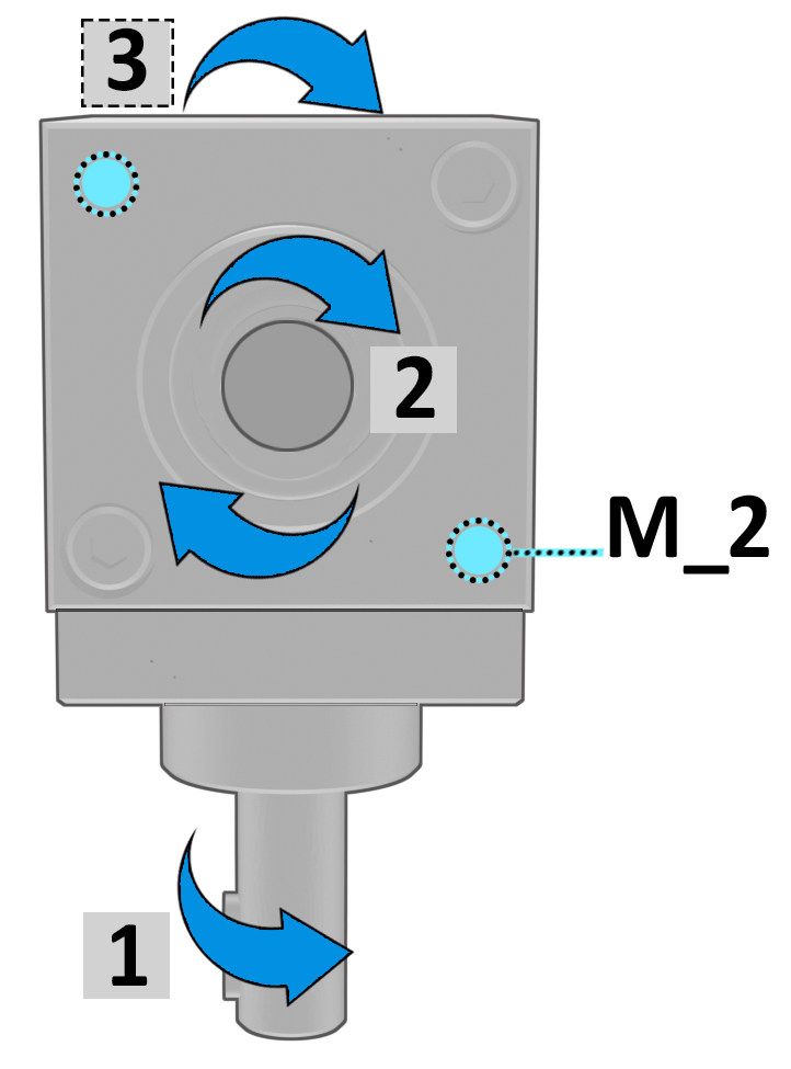
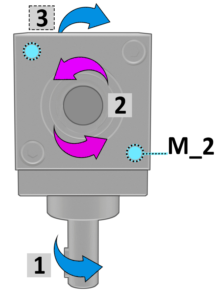
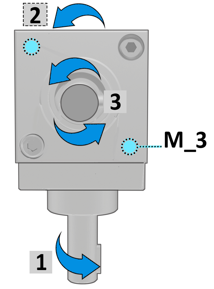
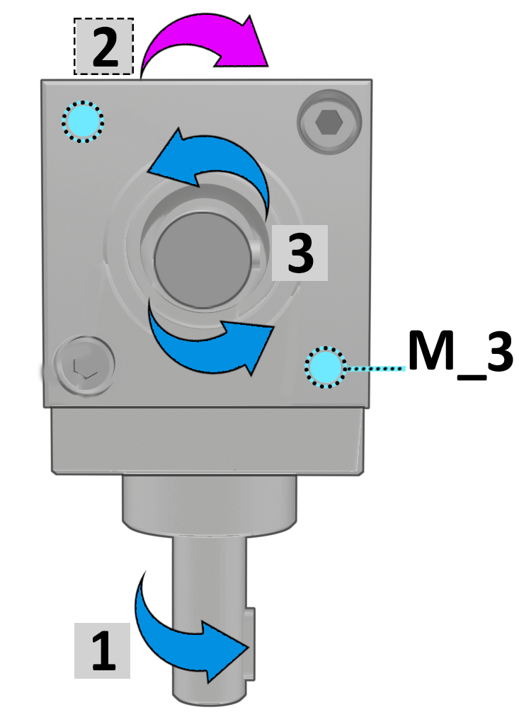
Shaft 1 is always shown on the side opposite the M_1 fixing bores and serves as the reference for determining: |
|
|
● the configuration |
|
|
● the direction of rotation |
|
|
● the gear ratio |
|
|
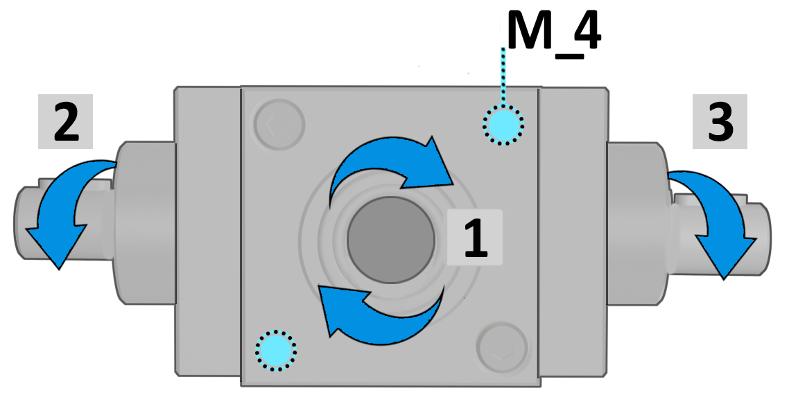
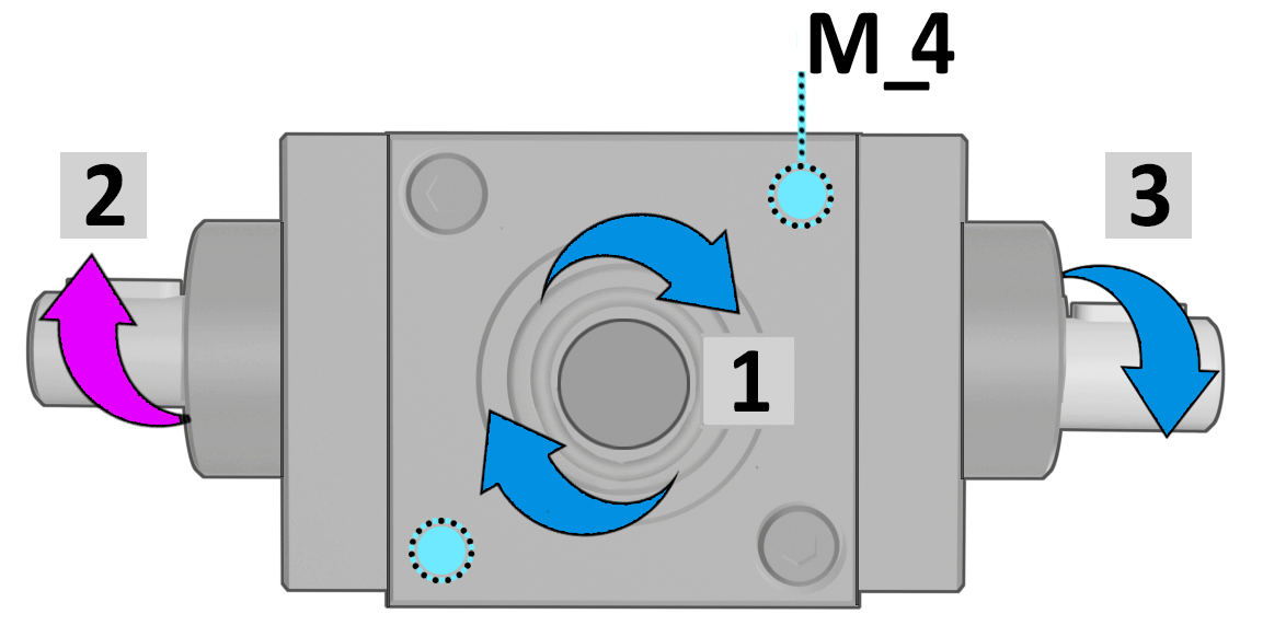
By convention, Shaft 1is shown rotating clockwise. The others shaft are defined following the clockwise direction. |
|
|
AVAILABLE TRANSMISSION RATIOS |
Tab.3 |
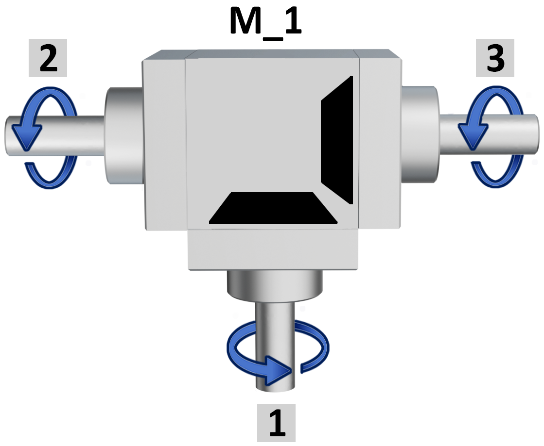
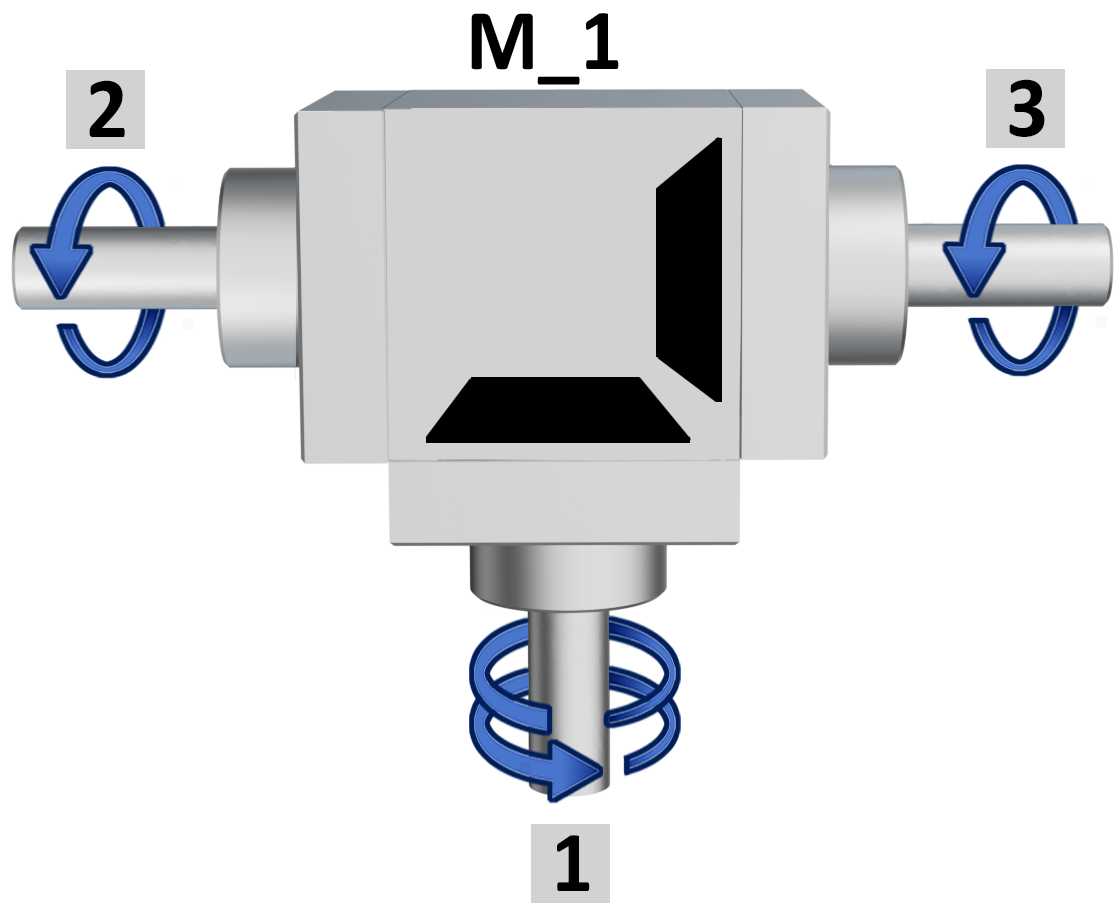
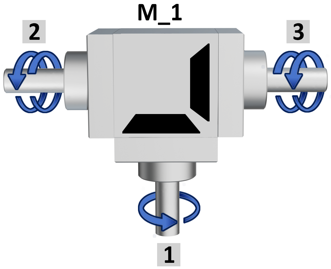
 The ratio is determined by the shaft1always shown on the opposite side of the fixing bores M_1. The ratio is determined by the shaft1always shown on the opposite side of the fixing bores M_1. |
||
| Ratio 1/1 | Ratio 1/2 | Ratio 2/1 |
 |
 |
 |
|
Example |
Example |
Example |
| Shaft 1 = 10 rpm | Shaft 1 = 10 rpm | Shaft 1 = 5 rpm |
| Shafts 2-3 = 10 rpm | Shafts 2-3 = 5 rpm | Shafts 2-3 = 10 rpm |
| not available in version D | ||
| M_ FIXING POSITIONS | Tab.4 |
|
|
| M_1 = top view. 0° | M_2 = right side view 90° | |||
 |
 |
+90° →DX |
 |
 |
| same rotation | opposite rotation | same rotation | opposite rotation | |
|
↑ +90° |
+90° ↓ |
|||
| M_3 = left side view 270° | M_4 = bottom view 180° | |||
 |
 |
+90° ← SX |
|
|
| same rotation | opposite rotation | same rotation | opposite rotation | |
|
PHASE BETWEEN KEYS |
|||
|
ratio |
degrees ° |
 |
 |
|
1/1 |
± 7,2° |
||
|
1/2 |
± 6,9° |
||
|
2/1 |
± 6,9° |
||
|
a. keyway |
|||
|
The keyways on the shafts are never perfectly in phase, except for shaft 2 and 3 in versions «B» and «D». |
|||
|
GUIDELINES |
|
Selection of the gearbox |
|
For correct sizing it is necessary to identify: the power, the torque and the rotation speed. We advise to consult also the tables, and the technical data shown in the “General Information” (p. 4 - 7). |
|
Installation |
|
Ensure proper alignment of the shafts to avoid overloading, overheating, and premature wear of the bearings. The gearboxes, thanks to their construction design, can be installed in any position. |
|
Start-up |
|
After a brief pre-delivery test, the gearbox requires several hours of running to reach maximum efficiency. A gradual increase in load is recommended, reaching full load within 20-30 hours of operation. Initial temperatures will be higher during the break-in period. |
|
Periodic maintenance |
|
Our gearboxes are maintenance-free; however, it is advisable to periodically check for any lubricant leaks. The replacement of the gearbox depends on operating conditions, with an estimated lifespan of 10,000 hours under normal conditions. |
|
Storage |
|
During warehouse storage, protect the gearboxes from dust and corrosive environments. We recommend periodically rotating the gearboxes to ensure proper lubrication of internal parts and seals. |
|
Warranty |
|
The warranty is valid only if all instructions provided in the catalog are strictly followed. |
Richiedi l'accesso
|
EFFICIENCY DIAGRAMS AND TABLES |
|
| Output torque with ratio 1/1 | |
 |
|
| Output torque with ratio 1/2 | |
 |
|
| Output torque with ratio 2/1 | |
 |
|
LOADS DIAGRAMS AND TABLES |
|
|
Radial load ‹Fr› |
|
 |
|
| Axial load ‹Fa› | |
 |
|
| Representation of loads | |
|
«B» |
«D» |
 |
|
- The transmission efficiency of the gearbox is 90%. - The charts represent the maximum radial and axial loads applicable to the gearbox shaft. Note: a radial load (ex. belt tension) can only be applied to the long shaft of the «B» and «D» versions; otherwise, a support must be provided. |
|


