




66/8
Gearboxes for intermittent use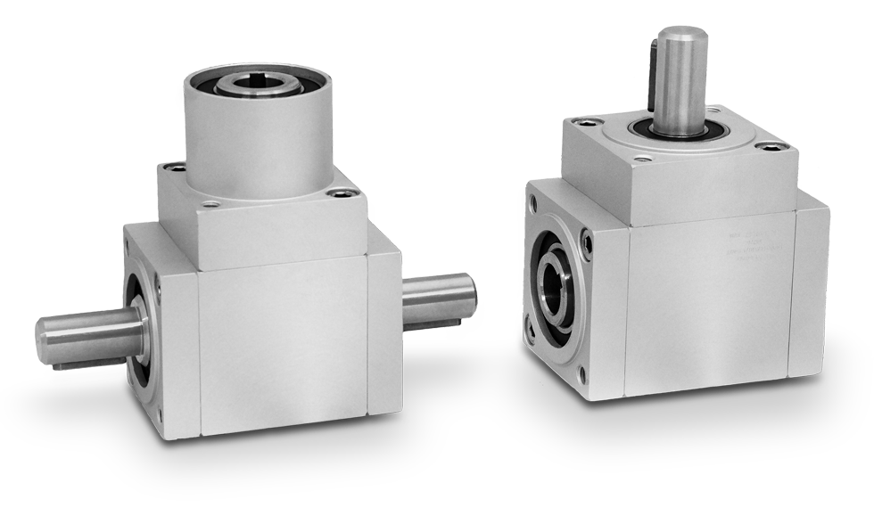
|
• Available transmission ratios: 1:1 - 1:2 (standard) - 2:1 (available in versions «A»-«B»-«C»). |
||
|
• Ratios 1/2 and 2/1 are only available with spiral gears. |
||
|
• Aluminium case, anodised; stainless steel shafts (standard). |
||
|
• Torque 90 Nm. Radial load 150 kg - axial load 15 kg. |
||
|
• Models: |
||
|
- Version «A» with 2 outputs; weight 2500 g. |
||
|
- Version «B» with 3 outputs; weight 2700 g. |
||
|
- Version «C» (opposite rotation) with 3 ouputs; weight 2770 g. |
||
|
- Version «D» with 3 outputs, 2 through hollow shafts; weight 2700 g. |
||
|
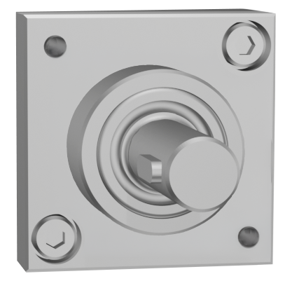
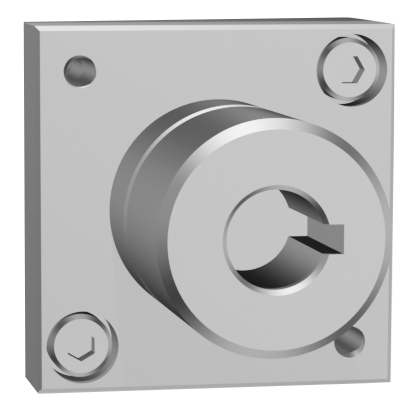
• Standard output shafts: M = male Ø14 / F = female Ø14. |
||
|
Available on request: |
|
|
|
▪ Case in stainless steel AISI 303. |
||
|
▪ Models with spiral bevel gears are available in all versions with transmission ratio 1/1. |
||
|
▪ Schmiernippel lieferbar in allen Ausführungen. |
Photogallery


|
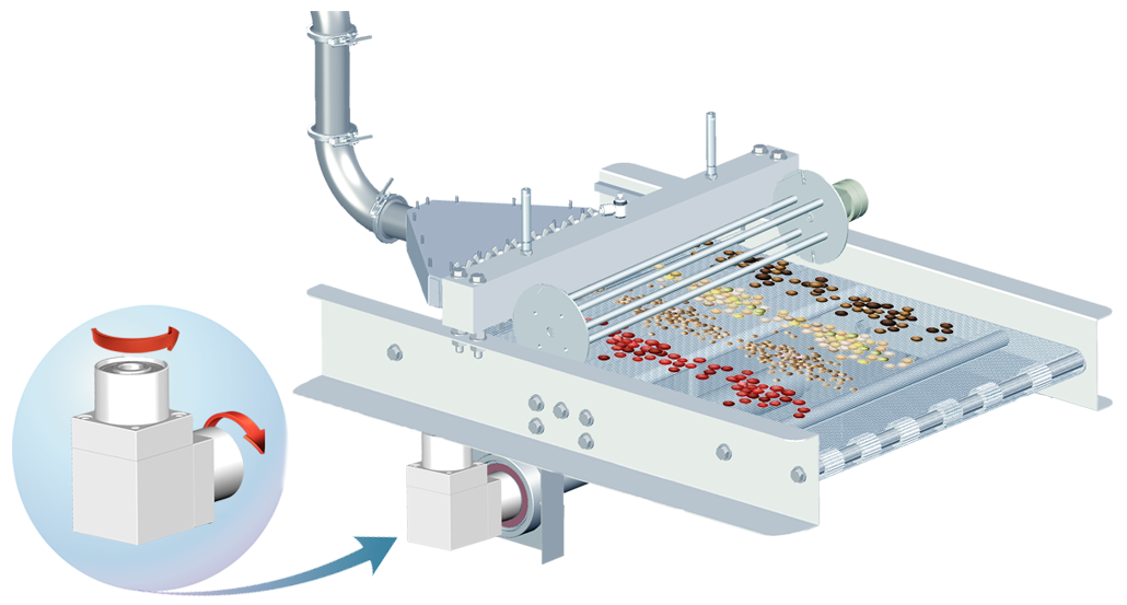
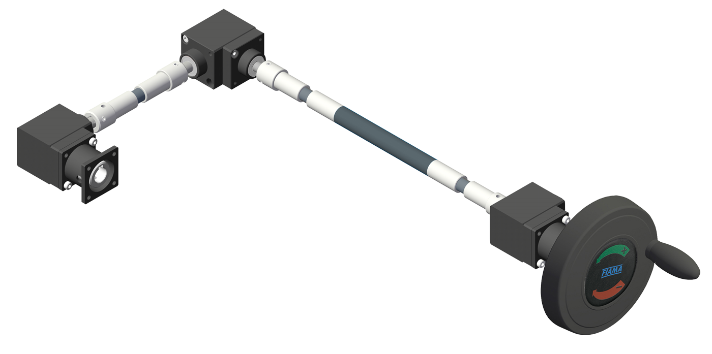
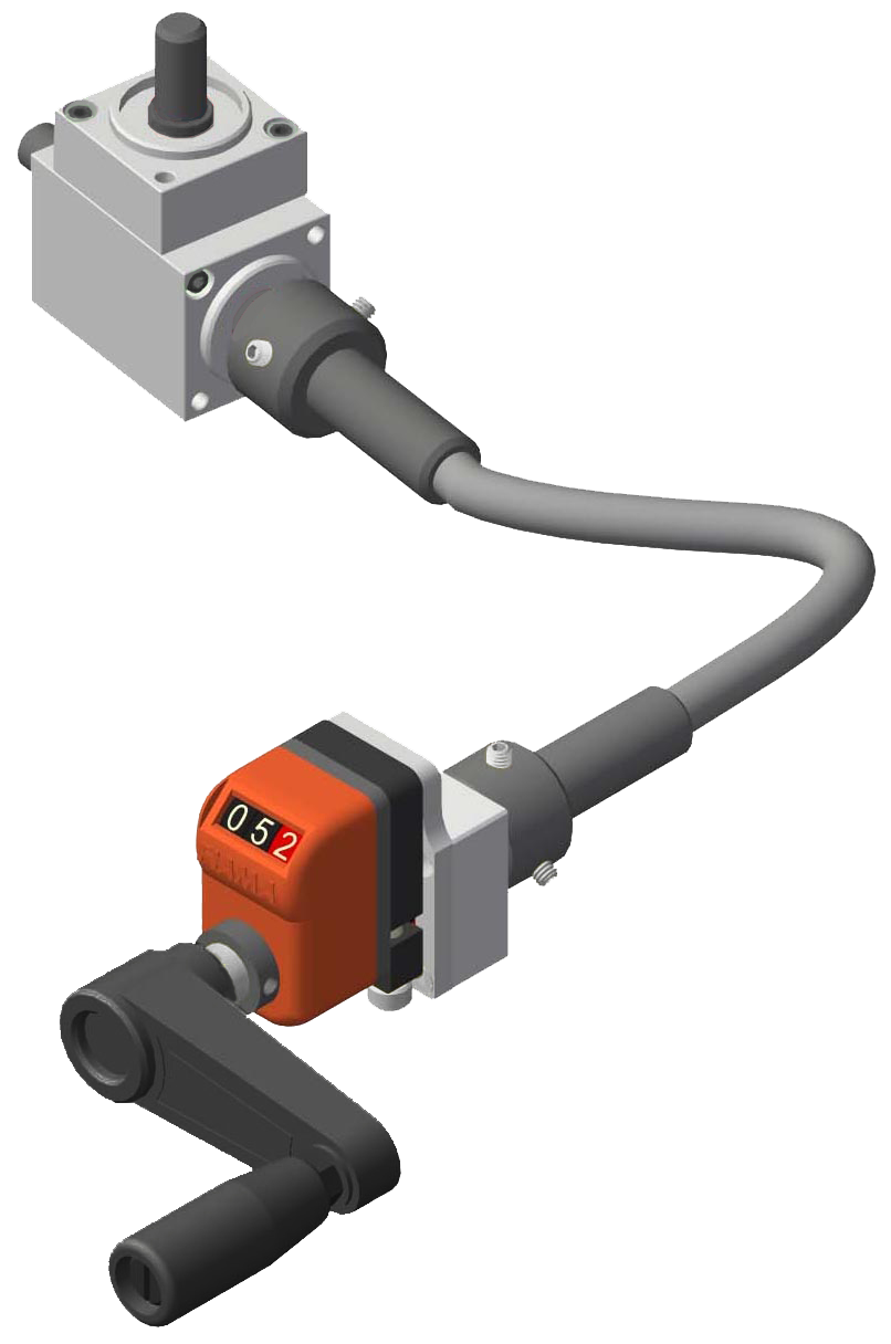
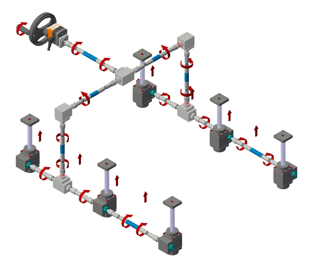
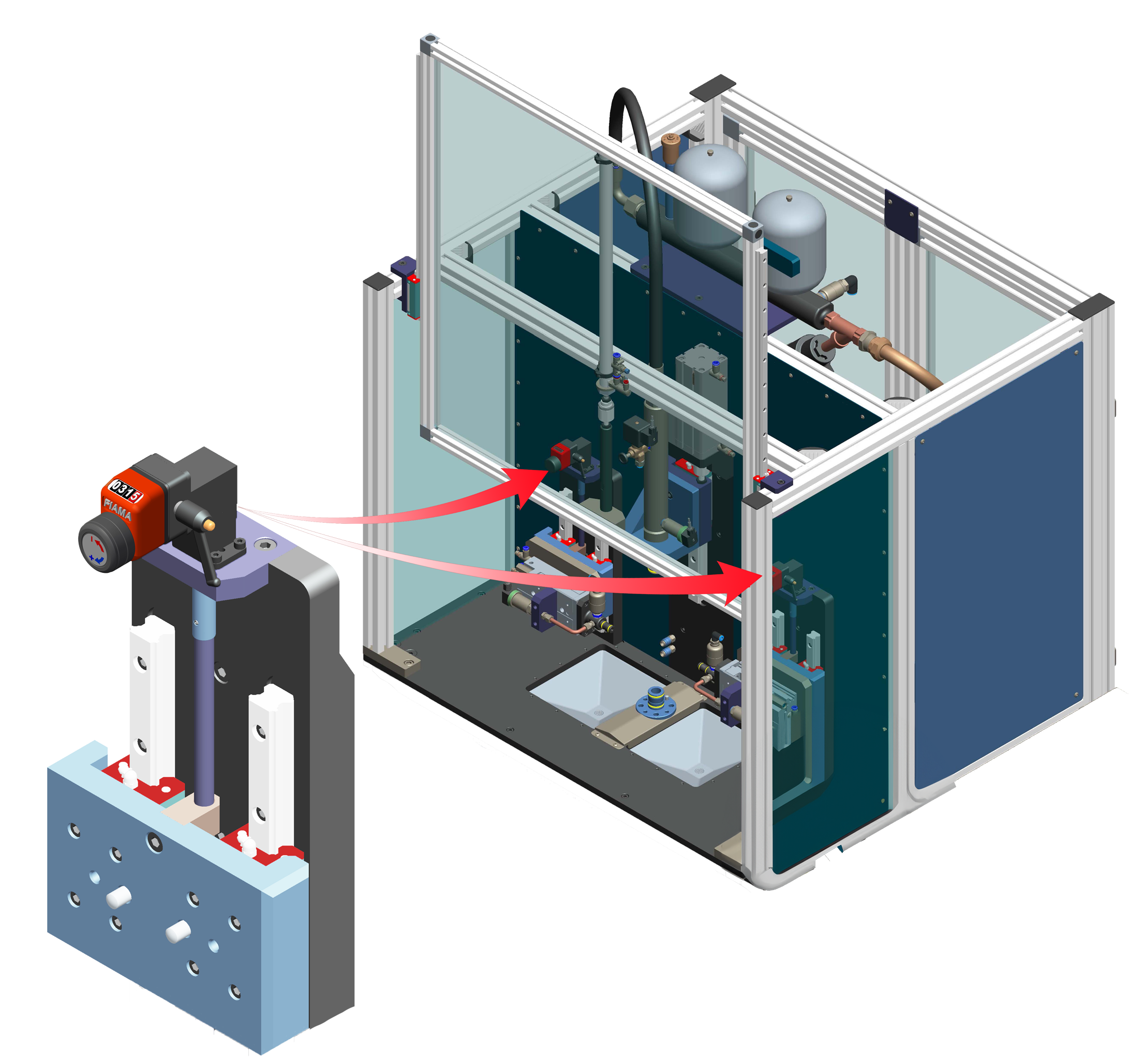
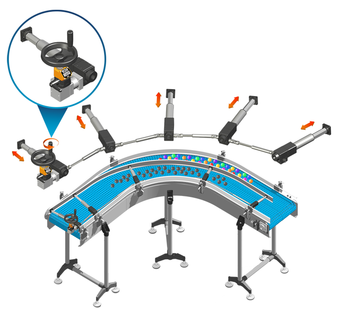
APPLICATION EXAMPLES |






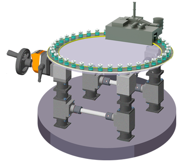
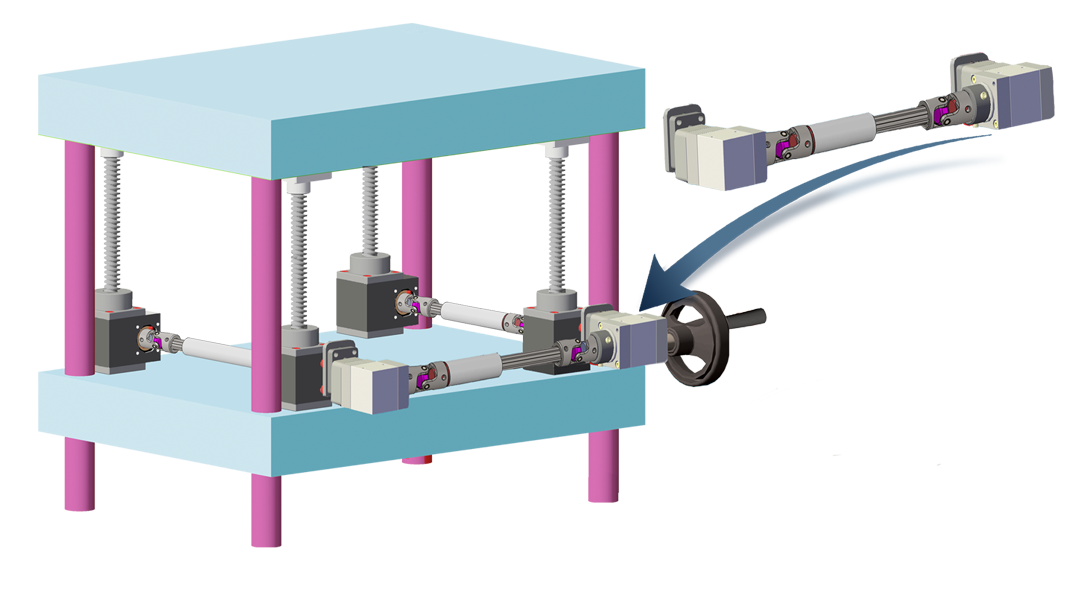
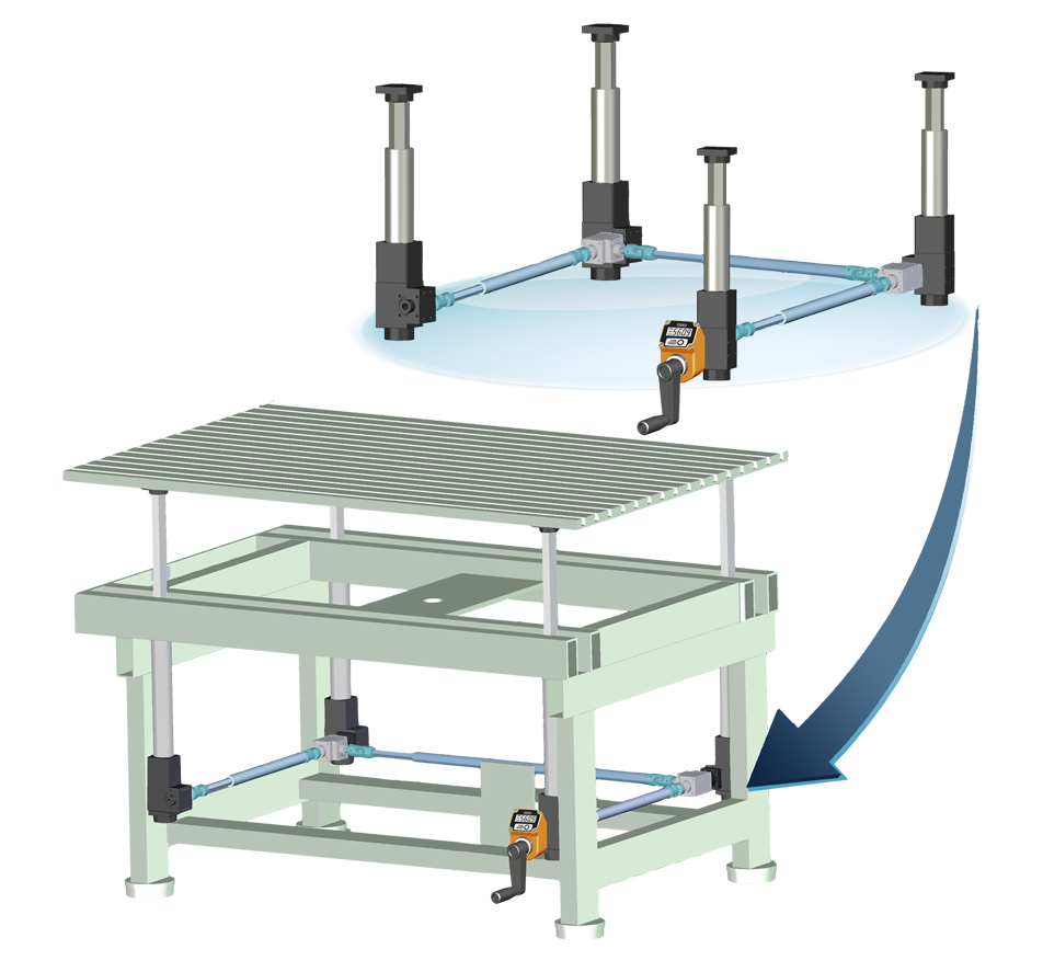
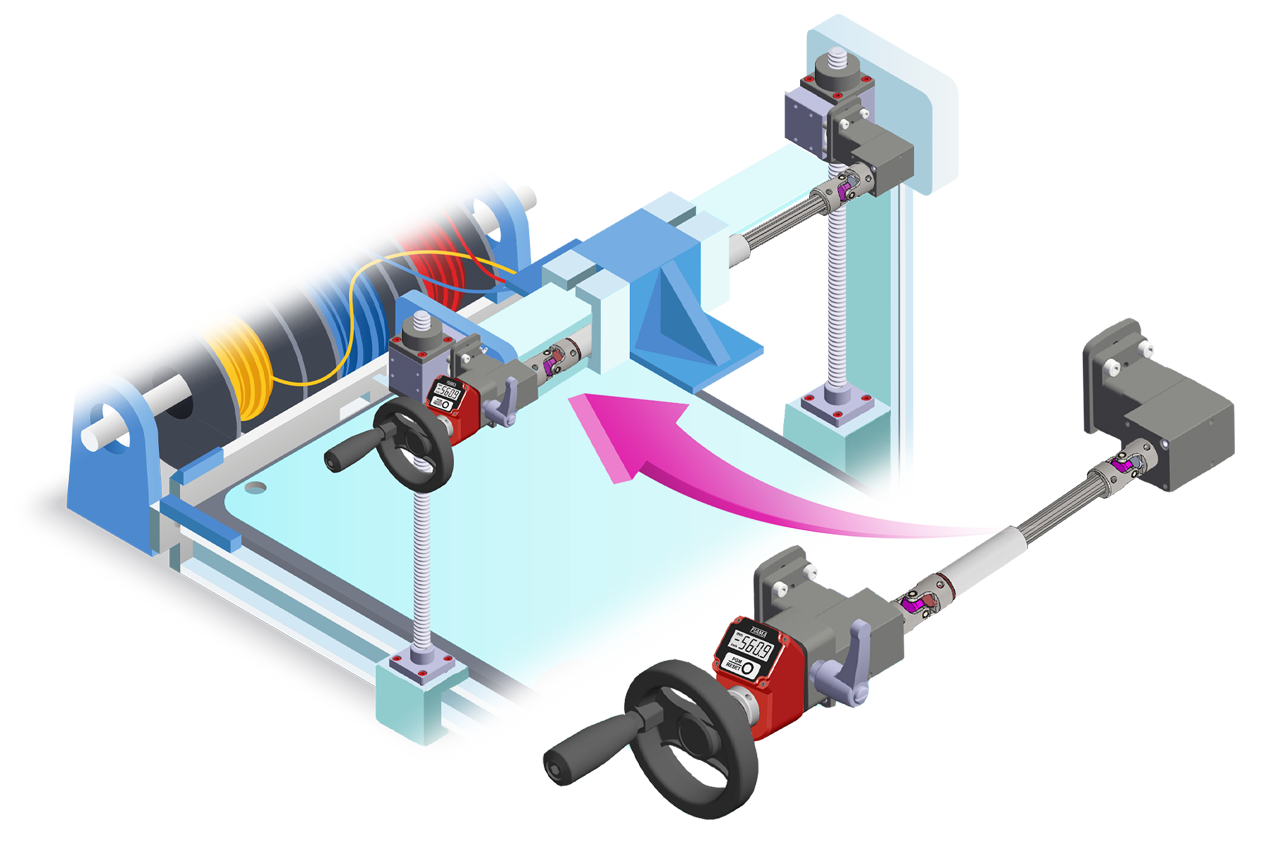
| AVAILABLE SHAFTS |
| M = male |
 |
| F = female |
 |
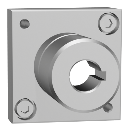
| F = female through shaft (available only on versione ⟪D⟫) |
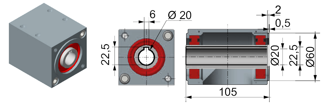 |
| DIMENSION DRAWINGS |
| VERSION ⟪A⟫ - M-M |
 |
| VERSION ⟪A⟫ - M-F |
 |
| VERSION ⟪A⟫ - F-F |
 |
| VERSION ⟪B⟫ - M-M-M |
 |
| VERSION ⟪B⟫ - F-M-M |
 |
| VERSION ⟪C⟫ - M-M-M with opposite rotation |
 |
| VERSION ⟪C⟫ - M-F-F with opposite rotation |
 |
| VERSION ⟪C⟫ - F-M-M with opposite rotation |
 |
| VERSION ⟪C⟫ - F-F-F with opposite rotation |
 |
| VERSION ⟪C⟫ - F-F-F with opposite rotation |
 |
| VERSION ⟪D⟫ - M-F-F with through-hollow shaft |
 |
| VERSION ⟪D⟫ - F-F-F with through-hollow shaft |
|
|
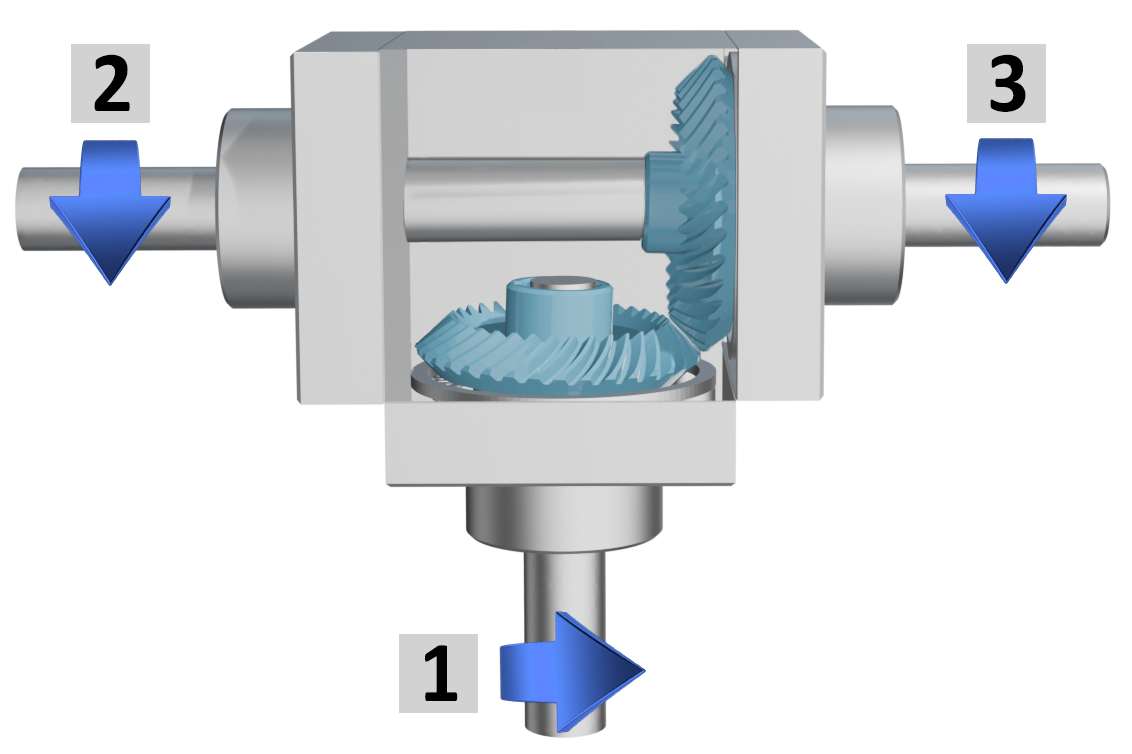
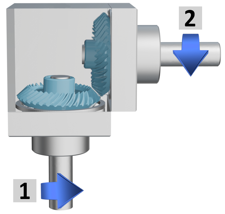
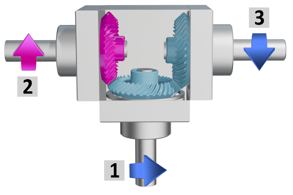
CONFIGURATION AND DIRECTION OF ROTATION |
Tab.1 |
||
| AVAILABLE VERSIONS | |
| ⟪A⟫ | ⟪B⟫ |
|
|
 |
|
2 outputs, same rotation direction |
3 outputs, same rotation direction |
| ⟪C⟫ | ⟪D⟫ |
|
|
|
|
3 outputs, 1 with opposite rotation directions |
3 outputs, 2 with through hollow shafts, same rotation direction |
|
|
|
|
OUTPUT SHAFT IDENTIFICATION |
Tab.2 |
| AVAILABLE OUTPUT SHAFTS | ||||||||
| male = M |
female blind = F |
through female = F |
||||||
 |
 |
 |
||||||
|
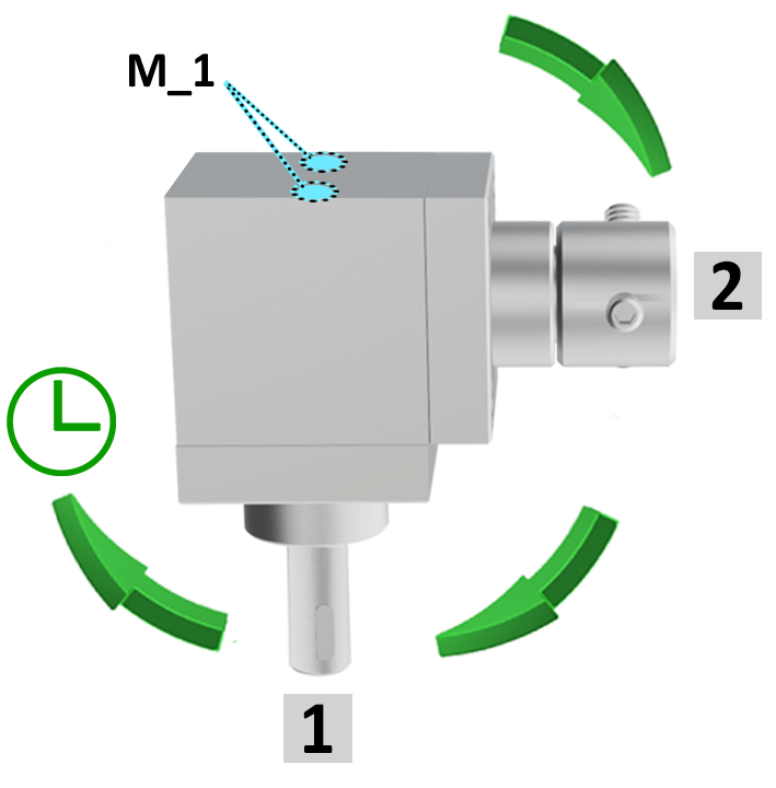
Example with 2 outputs |
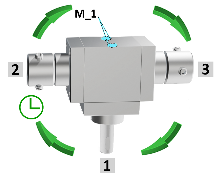
Example with 3 outputs |
 |
 |
|
|
|
|
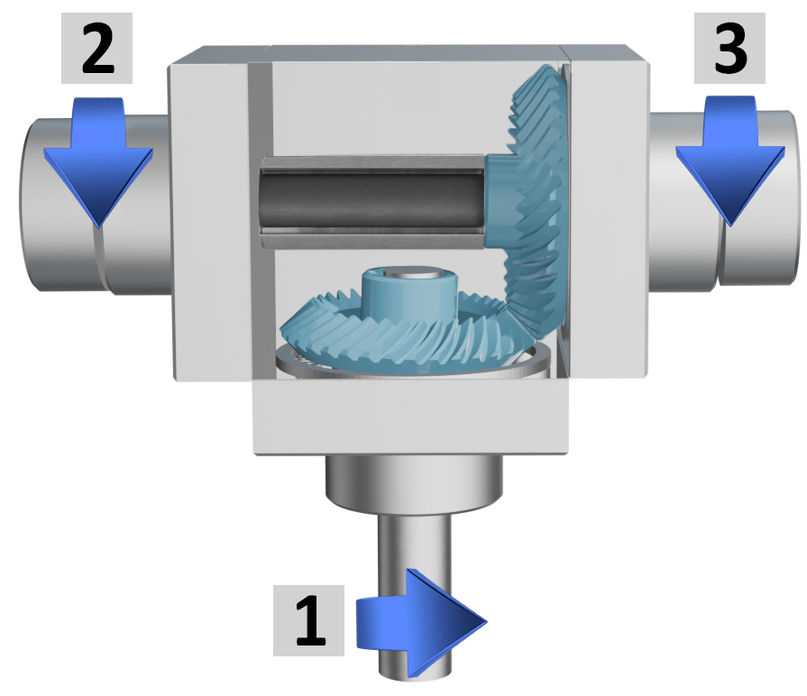
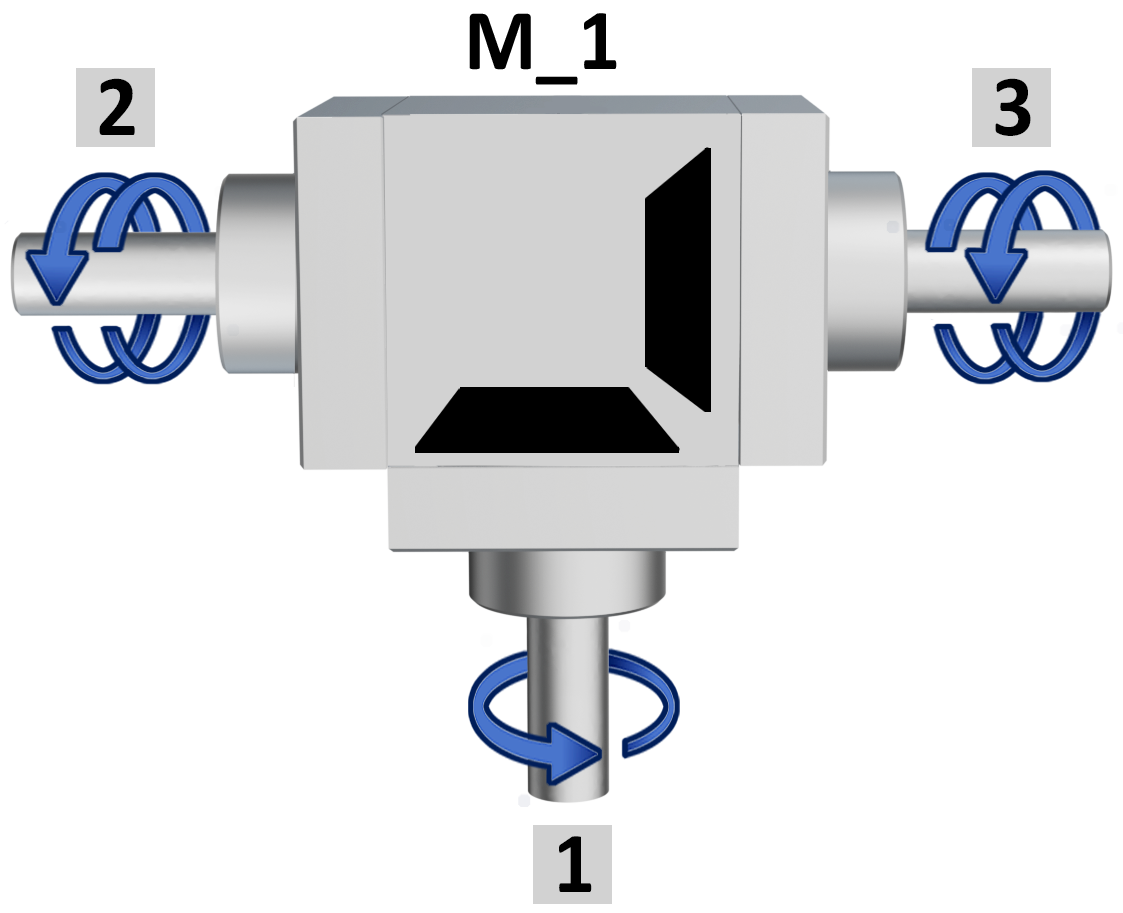
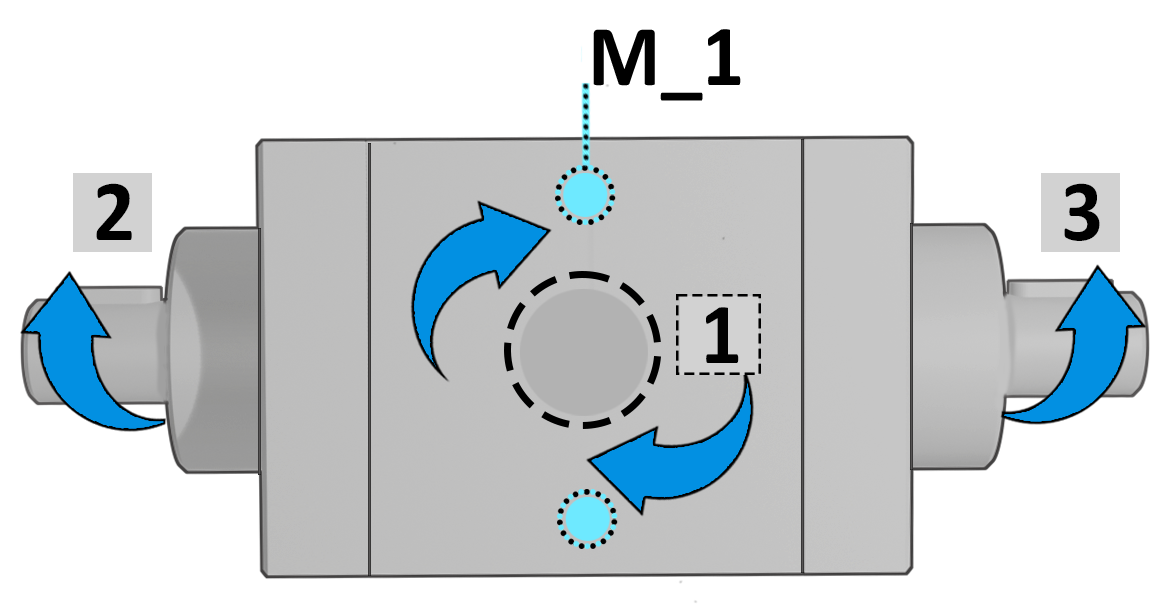
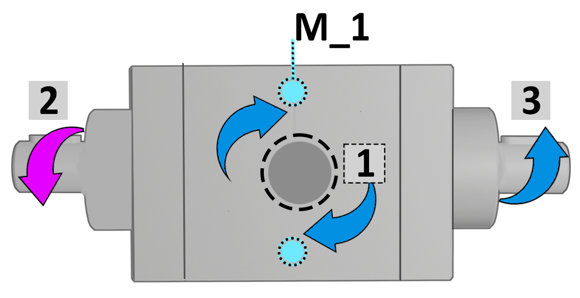
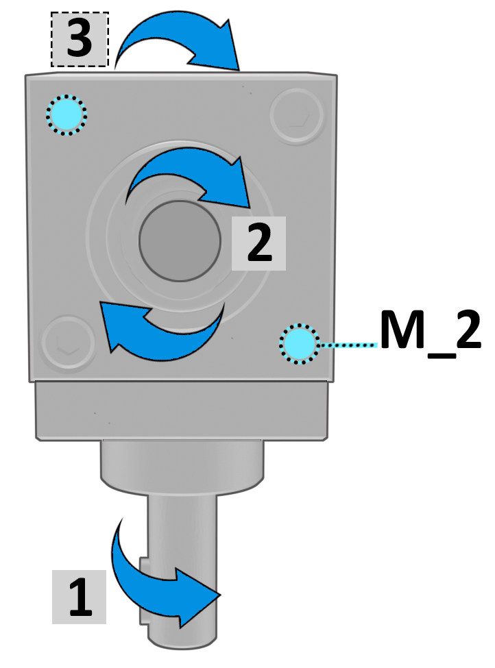
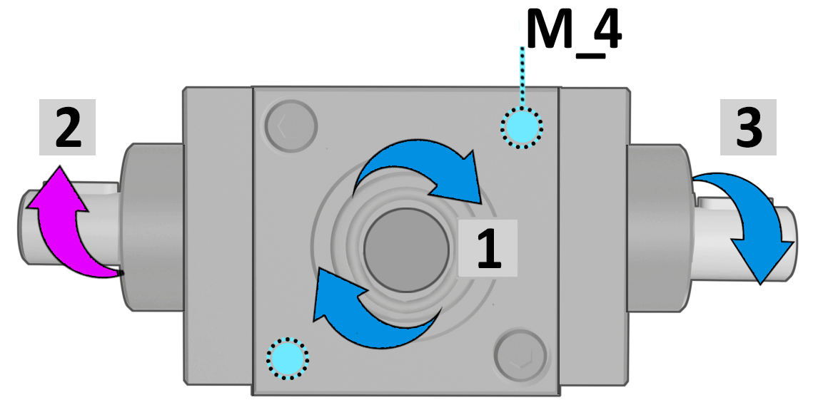
Shaft 1 is always shown on the side opposite the M_1 fixing bores and serves as the reference for determining: |
|
|
● the configuration |
|
|
● the direction of rotation |
|
|
● the gear ratio |
|
|
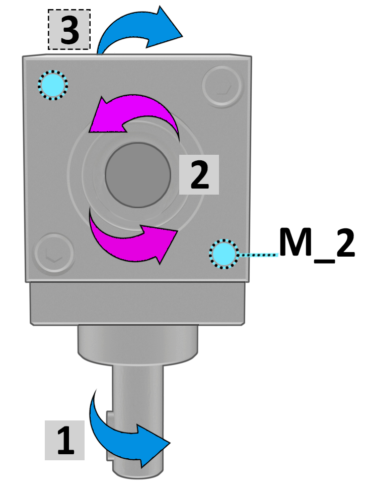
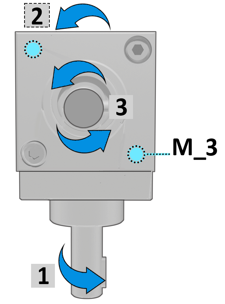
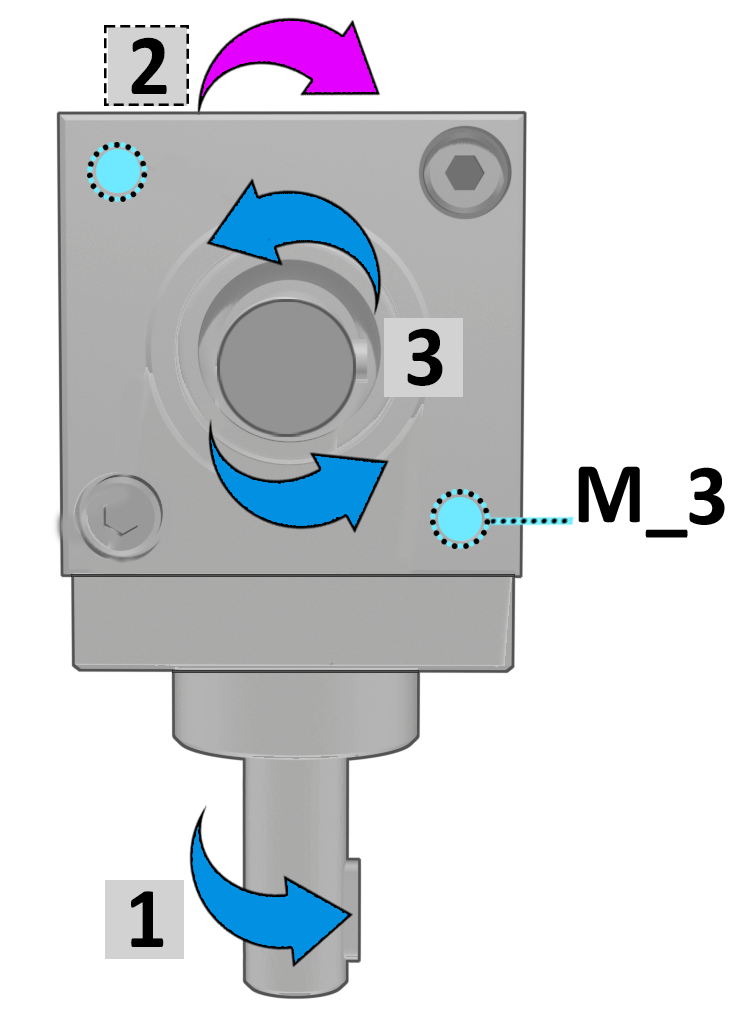
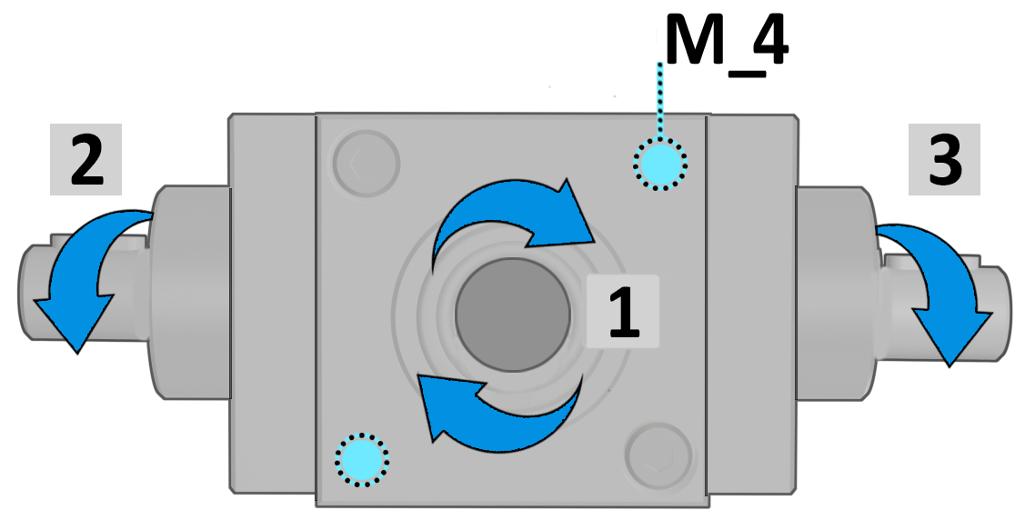
By convention, Shaft 1is shown rotating clockwise. The others shaft are defined following the clockwise direction. |
|
|
AVAILABLE TRANSMISSION RATIOS |
Tab.3 |
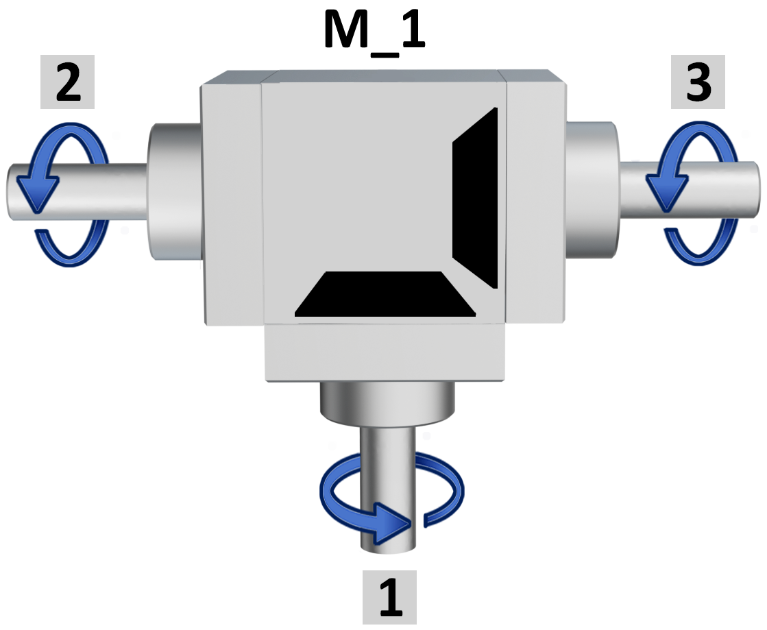
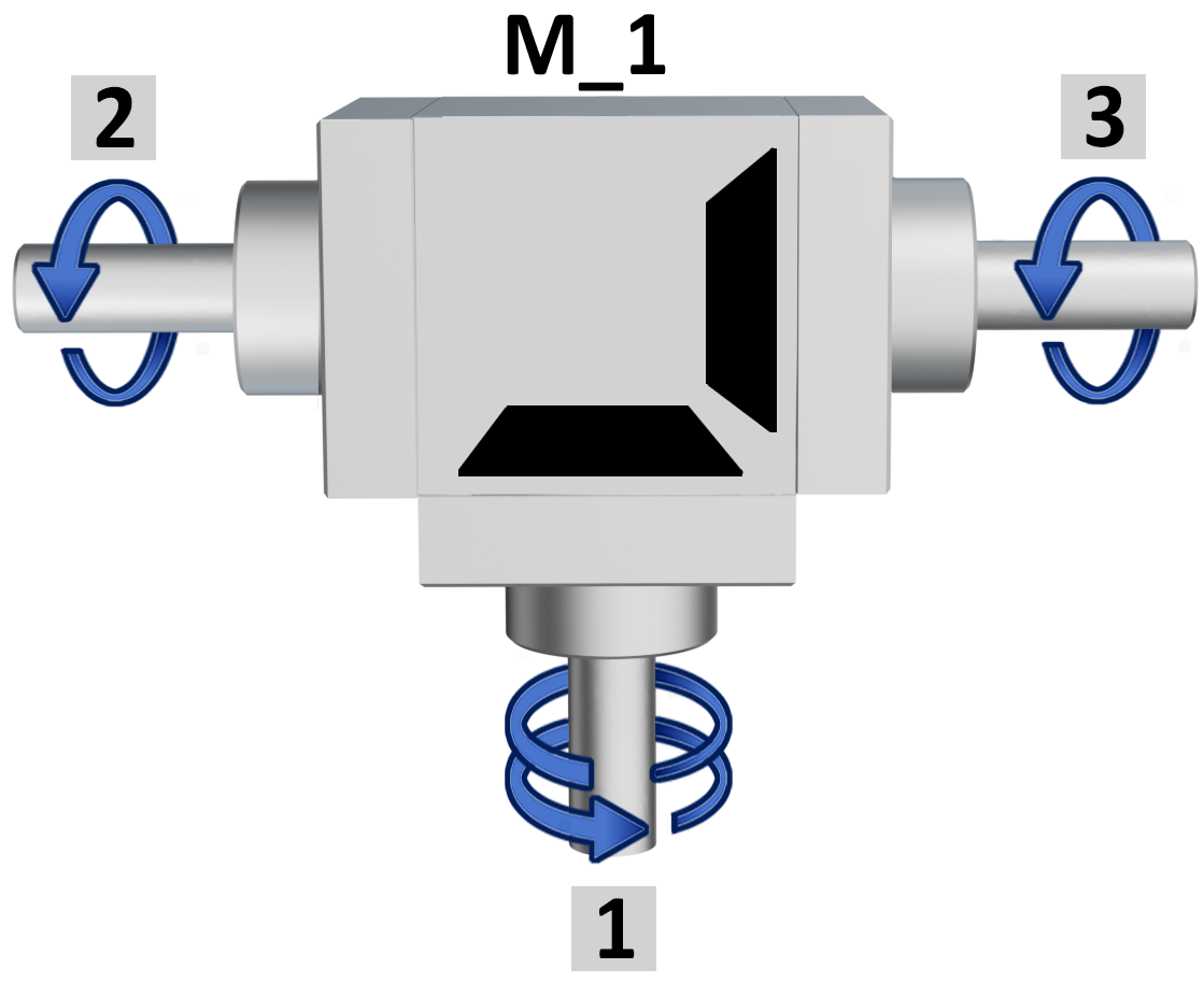
 The ratio is determined by the shaft1always shown on the opposite side of the fixing bores M_1. The ratio is determined by the shaft1always shown on the opposite side of the fixing bores M_1. |
||
| Ratio 1/1 | Ratio 1/2 | Ratio 2/1 |
 |
 |
 |
|
Example |
Example |
Example |
| Shaft 1 = 10 rpm | Shaft 1 = 10 rpm | Shaft 1 = 5 rpm |
| Shafts 2-3 = 10 rpm | Shafts 2-3 = 5 rpm | Shafts 2-3 = 10 rpm |
| not available in version D | ||
| M_ FIXING POSITIONS | Tab.4 |
|
|
| M_1 = top view. 0° | M_2 = right side view 90° | |||
 |
 |
+90° →DX |
 |
 |
| same rotation | opposite rotation | same rotation | opposite rotation | |
|
↑ +90° |
+90° ↓ |
|||
| M_3 = left side view 270° | M_4 = bottom view 180° | |||
 |
 |
+90° ← SX |
|
|
| same rotation | opposite rotation | same rotation | opposite rotation | |
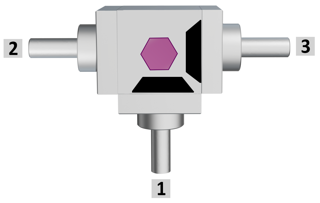
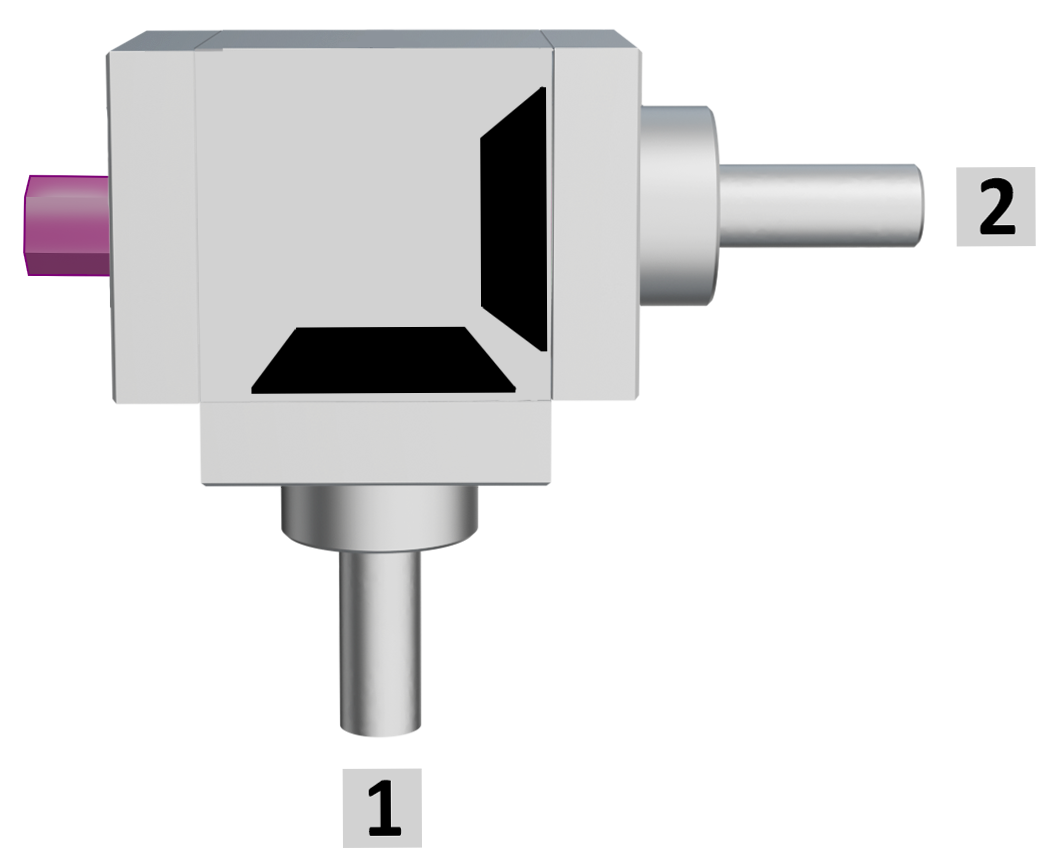
| GREASE NIPPLE POSITION | Tab.5 |
|
Gearboxes with 2 shafts |
Gearboxes with 3 shafts |
|
|
|
 |
|
|
For model 66/22 and 66/8 only: recommended for demanding conditions or extended service life. Periodically replenish the lubricant as instructed by our Technical Department. Supplied in the standard position shown; other positions on request. |
||


COUPLING BUSHES 2 piece bushing to couple gearboxes and shafts.
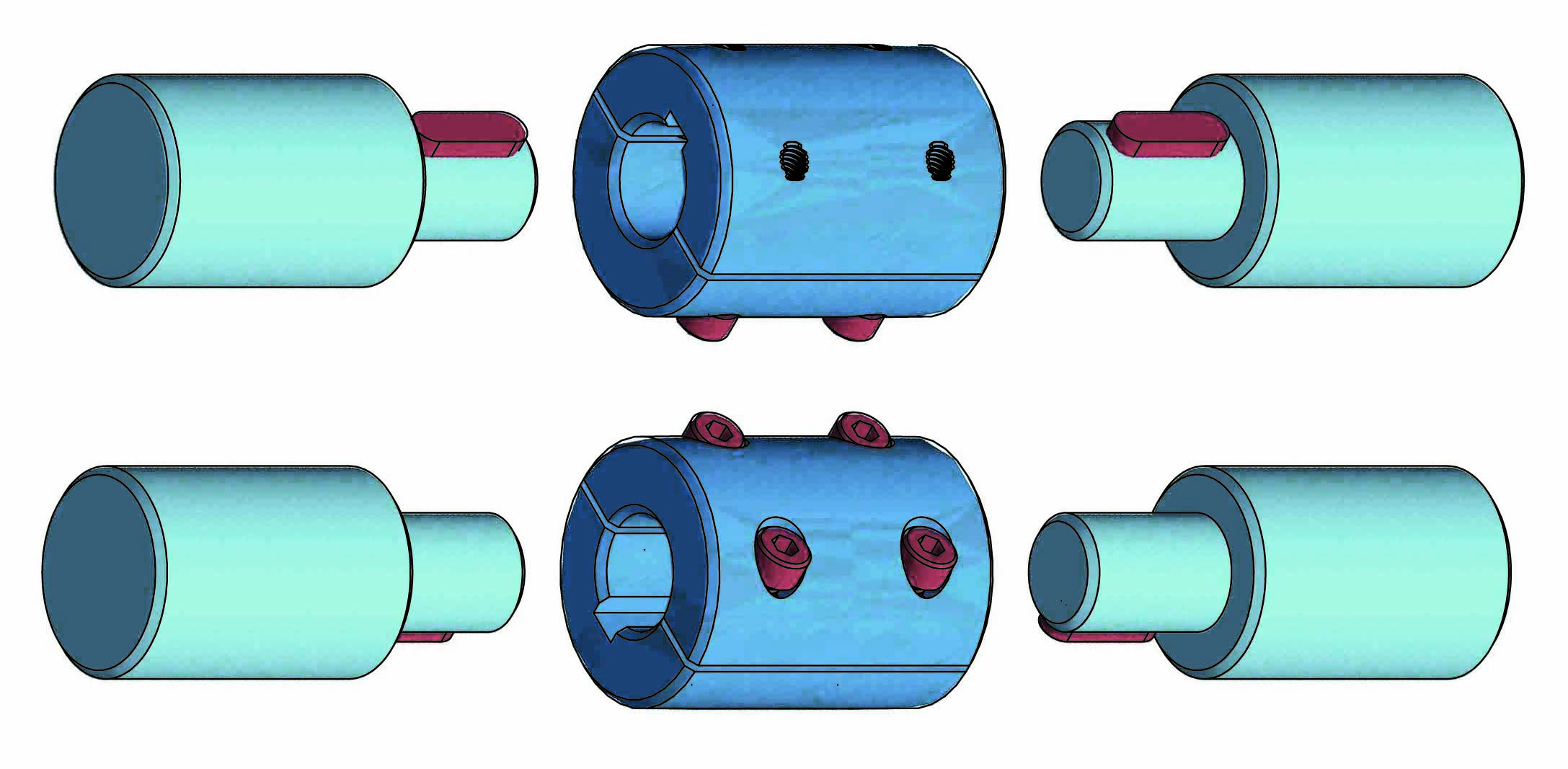
Available bores Ø: 6 - 8 -10 -14.
➜ for more complete information, see BT
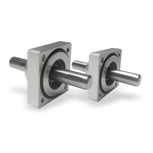
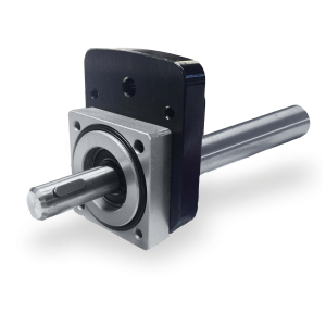
Flanged supports with extension shaft for coupling with position indicators.
➜ for more complete information, see Flanged supports
Richiedi l'accesso
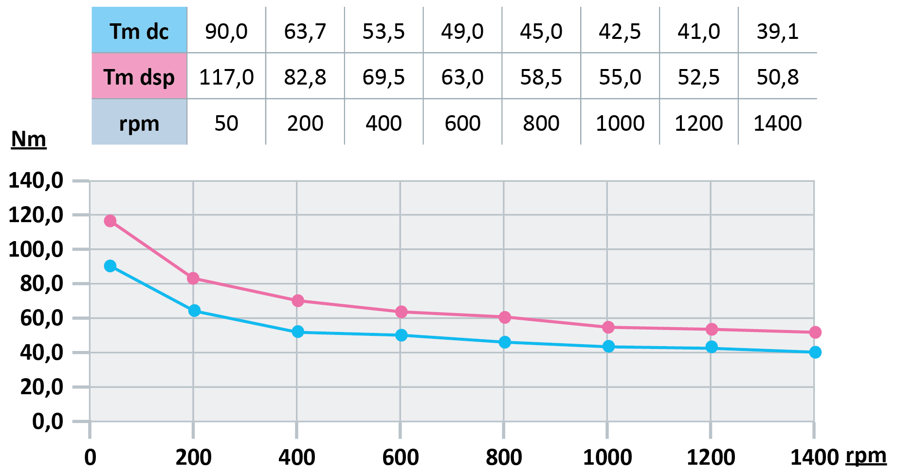
| OUTPUT TORQUE WITH RATIO 1/1 |
| OUTPUT TORQUE WITH RATIO 1/2 |

| OUTPUT TORQUE WITH RATIO 2/1 |

| Efficiency = 90% |
| - Tm = maximum torque in Nm |
| - dc = bevel gearing |
| - dsp = spiral gearing |


