66/6
Gearboxes for intermittent use
|
• Available transmission ratios: 1:1 - 1:2 (standard) - 2:1 (available in versions «A»-«B»-«C»). |
||
|
• Ratios 1/2 and 2/1 are only available with spiral gears. |
||
|
• Aluminium case, anodised; stainless steel shafts (standard). |
||
|
• Torque 45 Nm. Radial load 75 kg - axial load 7,5 kg. |
||
|
• Models: |
||
|
- Version «A» with 2 outputs; weight 330 g. |
||
|
- Version «B» with 3 outputs; weight 520 g. |
||
|
- Version «C» (opposite rotation) with 3 ouputs; weight 535 g. |
||
|
- Version «D» with 3 outputs, 2 through hollow shafts; weight 520 g. |
||
|
• Standard output shafts: M = male Ø14 / F = female Ø14. |
||
|
Available on request: |
|
|
|
▪ Case in stainless steel AISI 303. |
||
|
▪ Models with spiral bevel gears are available in all versions with transmission ratio 1/1. |
|
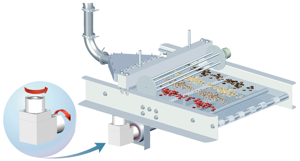
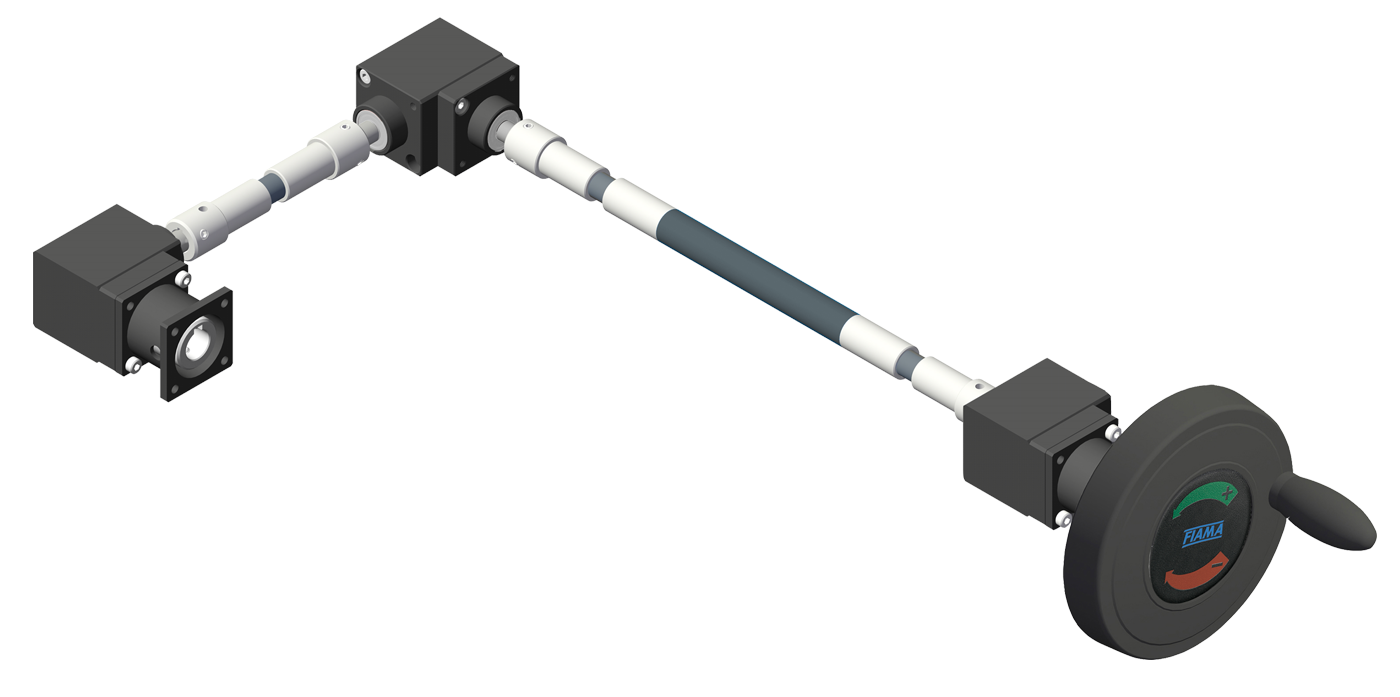
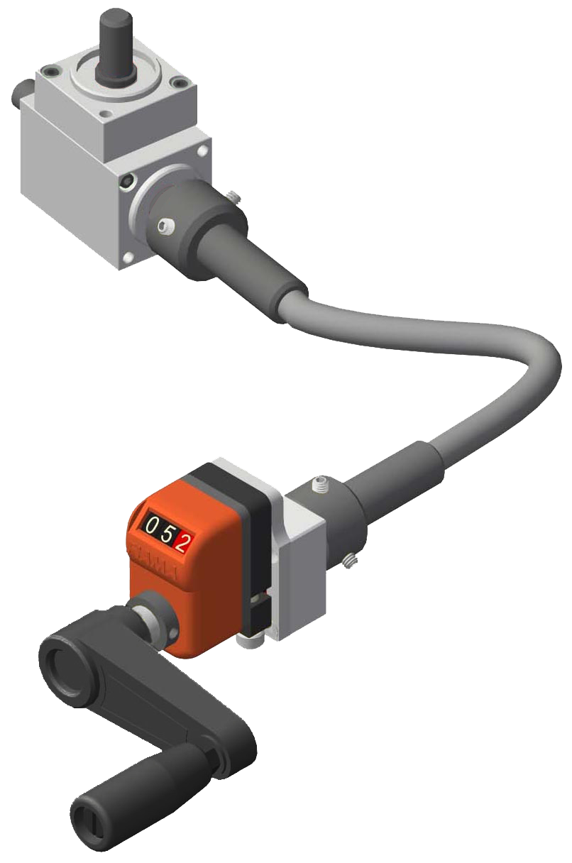
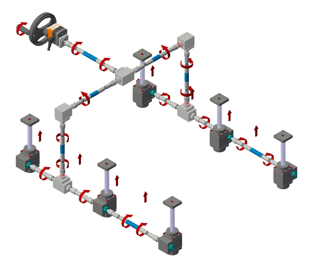
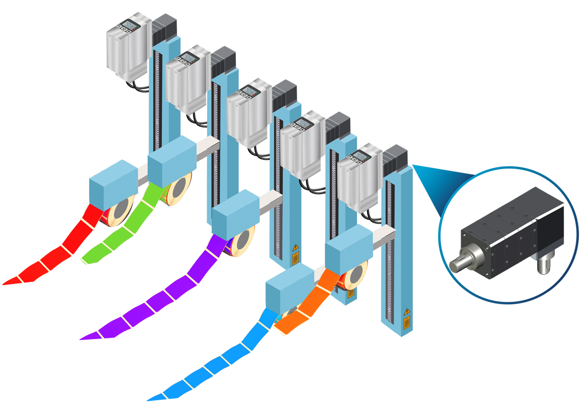
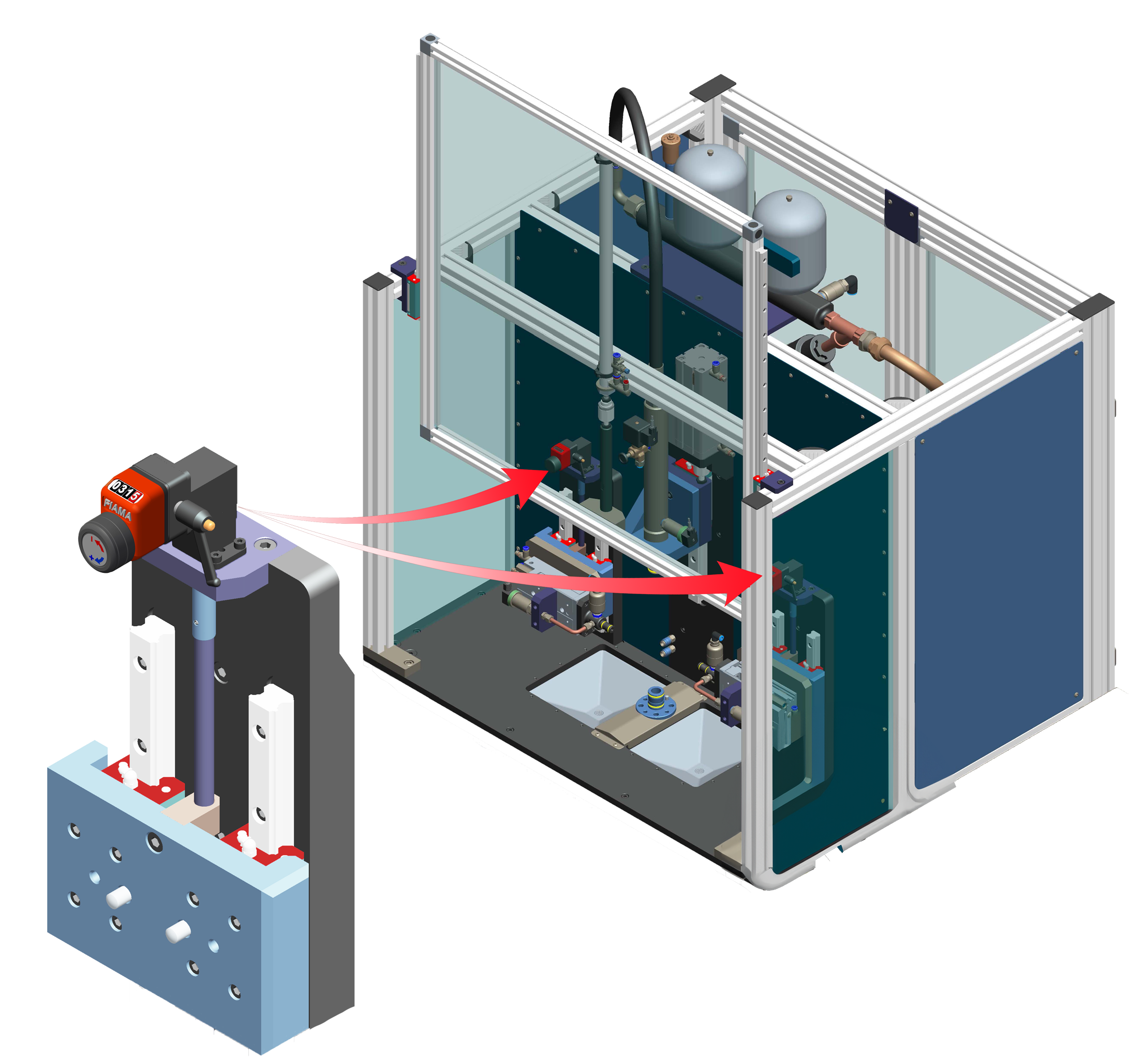
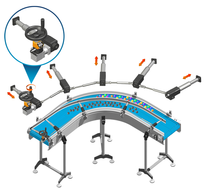
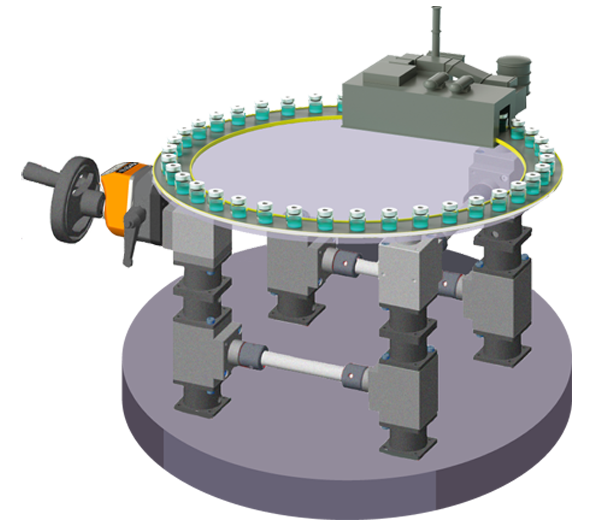
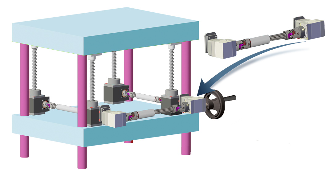
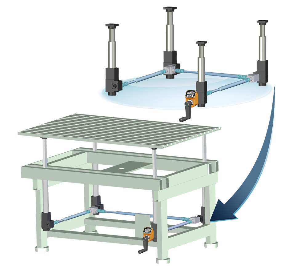
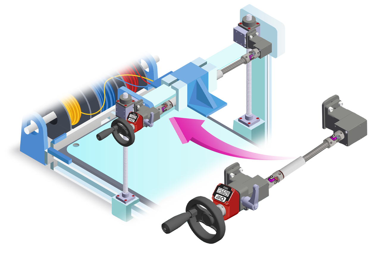
APPLICATION EXAMPLES |





| AVAILABLE SHAFTS |
| M = male |
 |
| F = female |
 |
| F = female through shaft (available only on versione ⟪D⟫) |
 |
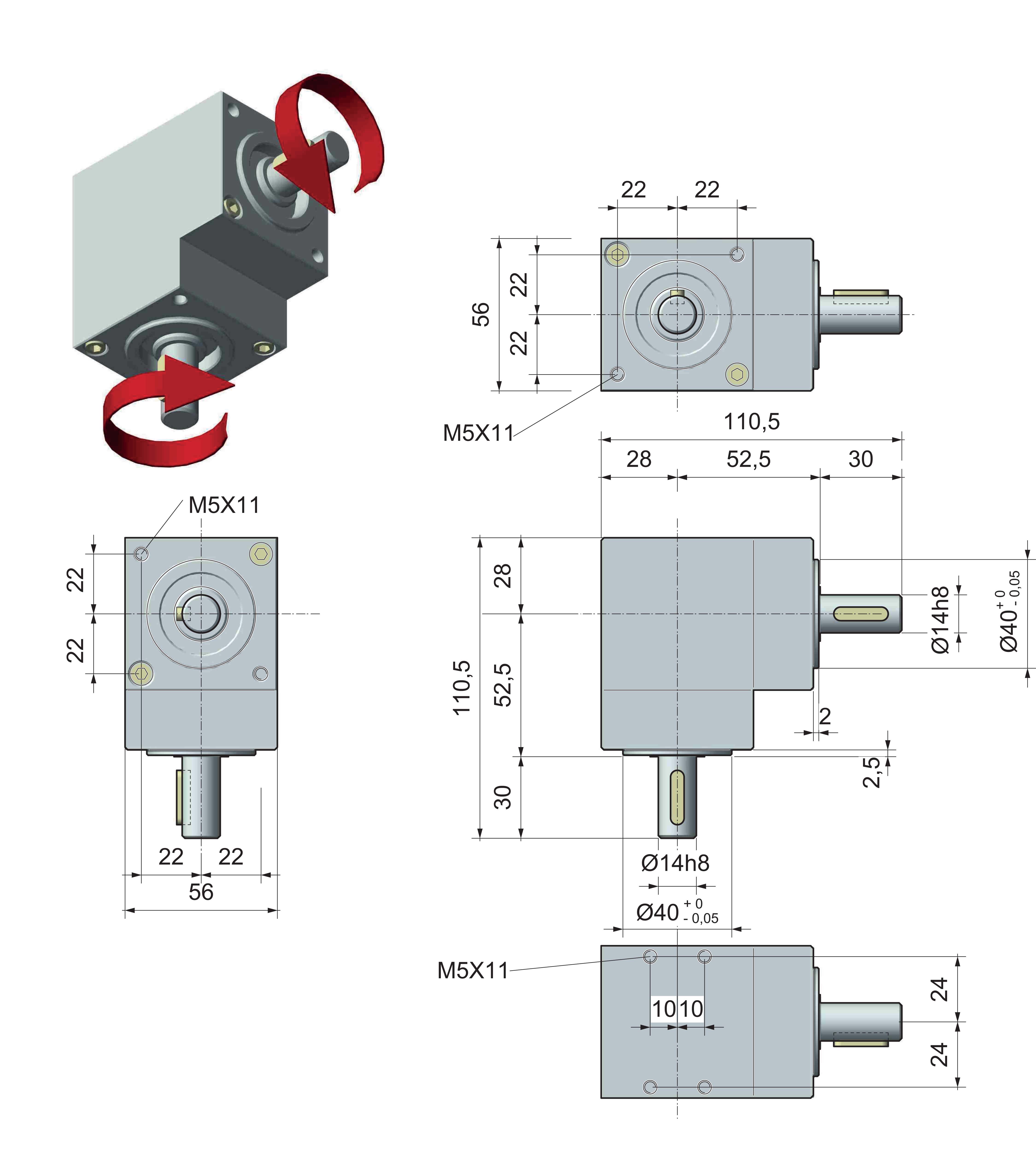
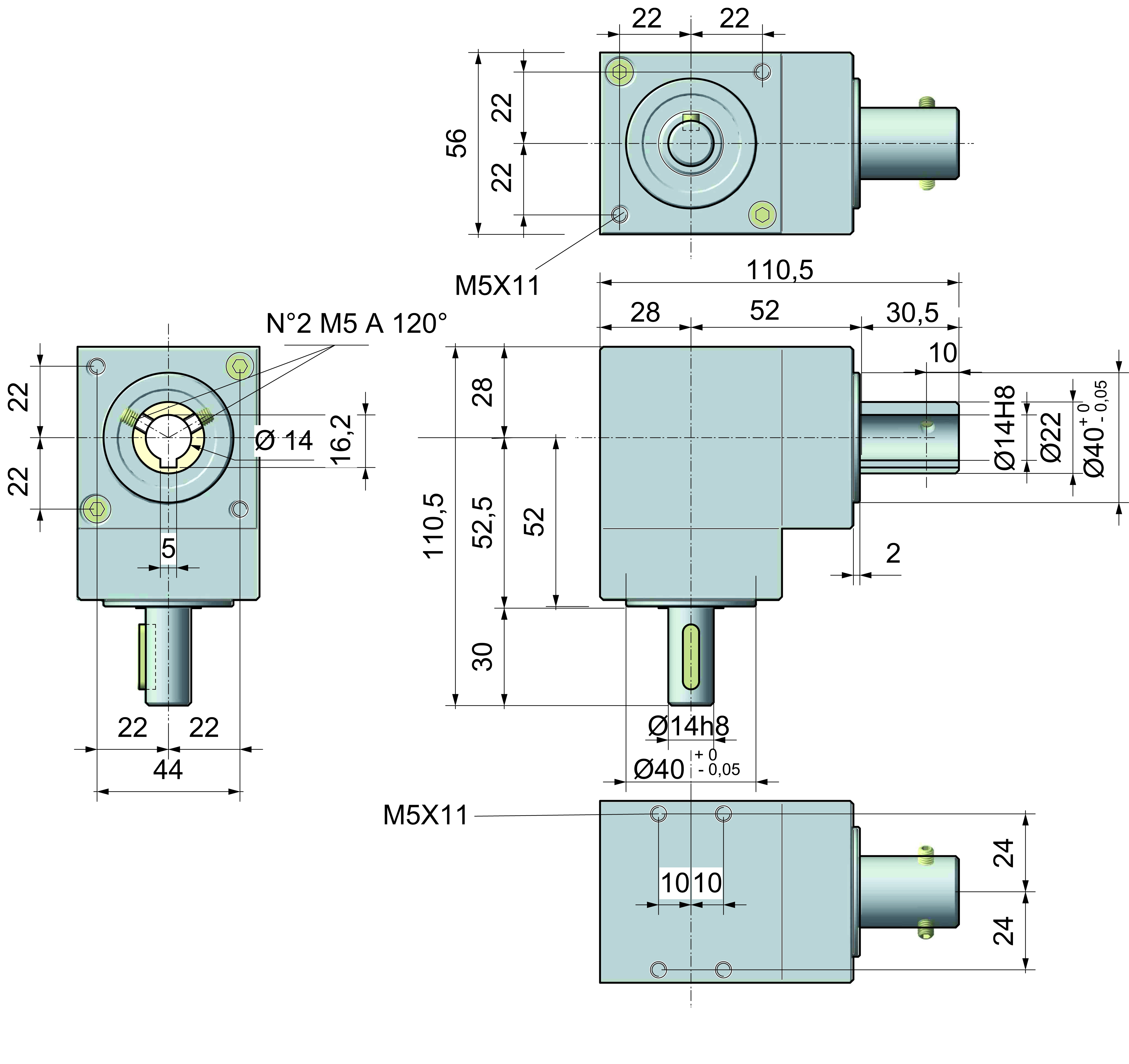
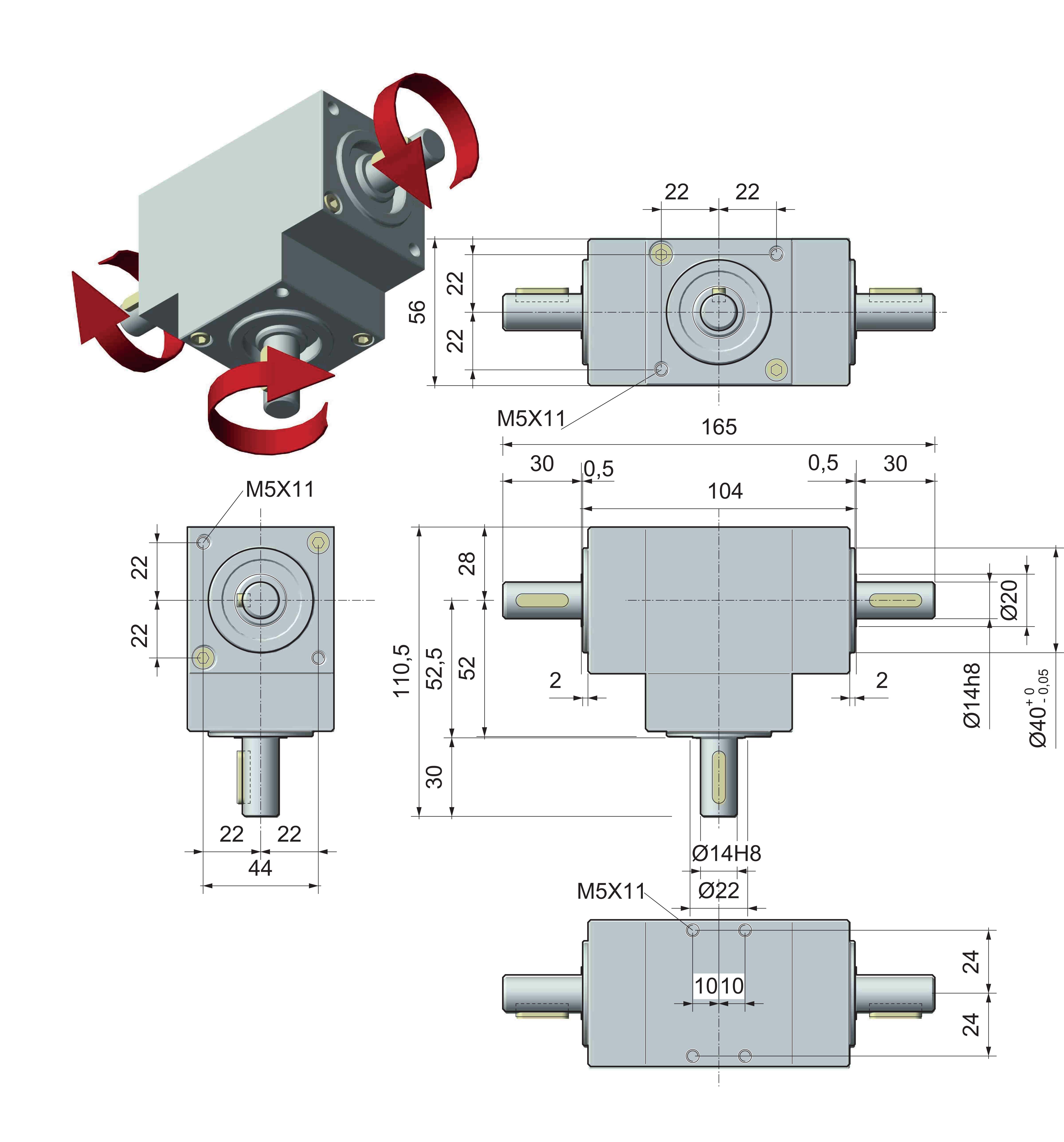
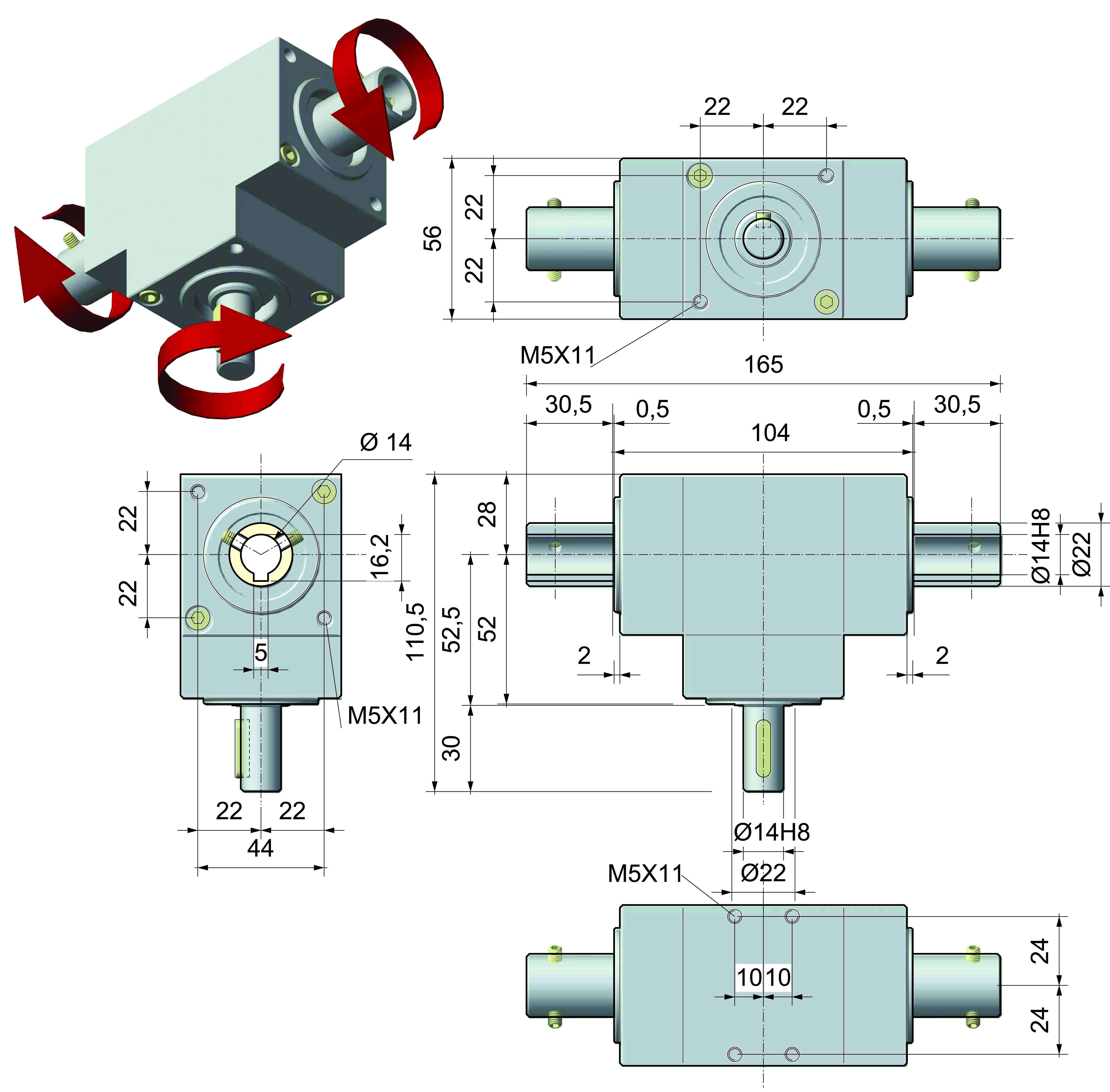
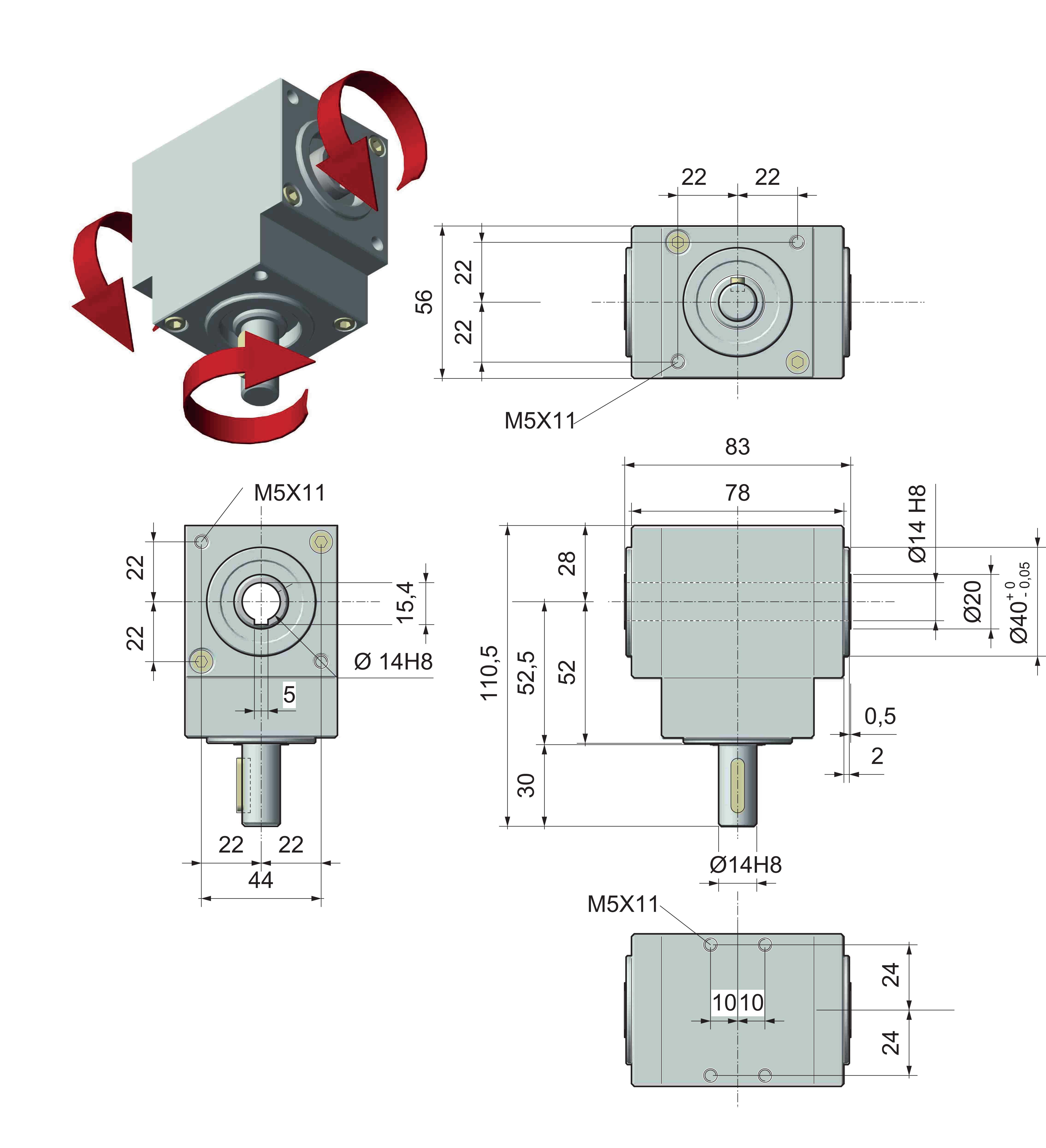
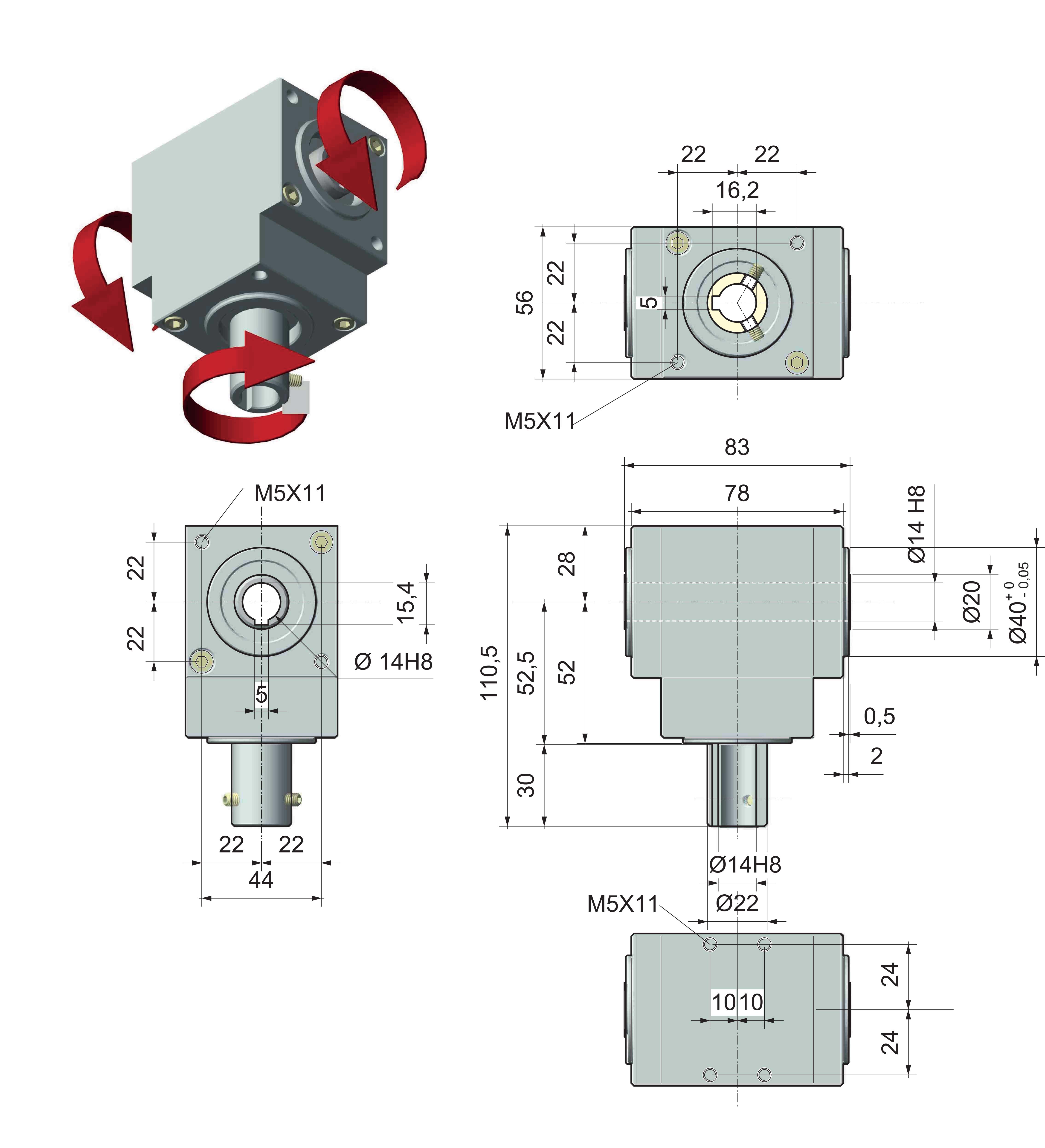
| DIMENSION DRAWINGS |
| VERSION ⟪A⟫ - M-M |
 |
| VERSION ⟪A⟫ - M-F |
 |
| VERSION ⟪A⟫ - F-F |
 |
| VERSION ⟪B⟫ - M-M-M |
 |
| VERSION ⟪B⟫ - F-M-M |
 |
| VERSION ⟪C⟫ - M-M-M with opposite rotation |
 |
| VERSION ⟪C⟫ - M-F-F with opposite rotation |
 |
| VERSION ⟪C⟫ - F-M-M with opposite rotation |
 |
| VERSION ⟪C⟫ - F-F-F with opposite rotation |
 |
| VERSION ⟪D⟫ - M-F-F with through-hollow shaft |
 |
| VERSION ⟪D⟫ - F-F-F with through-hollow shaft |
 |
| CONFIGURATION AND DIRECTION OF ROTATION | ||||||
| ⟪A⟫ | ⟪B⟫ | ⟪C⟫ | ⟪D⟫ | |||
 |
||||||
| The direction of rotation depends from the configuration and from the positioning.. |
|
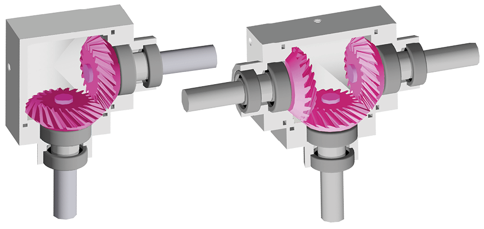
REPRESENTATION OF BEVEL GEARS |
|||
| Straight bevel gears | Spiral bevel gears ‹SP› | ||
 |
 |
||
|
Suitable for moderate loads and speeds |
Suitable for loads + 30% and high speeds |
||
|
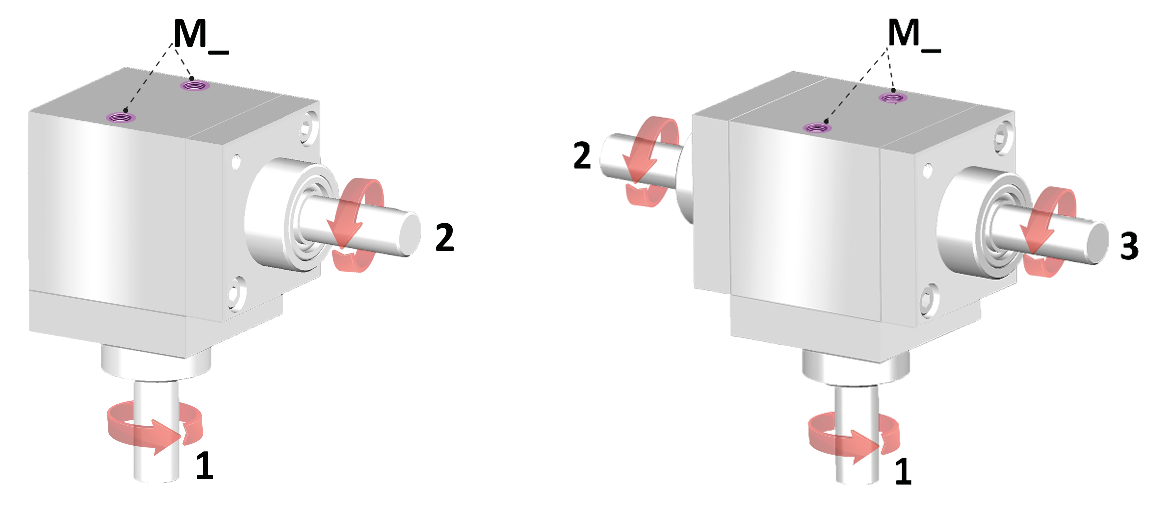
REPRESENTATION OF TRANSMISSISSION RATIOS |
|
|
 |
|
|
The ratio depends on shaft ‹1› shown opposite the fixing bores M_ |
|
|
example: ratio 1:2 |
example: ratio *2:1 |
|
shaft 1 = 10 rpm |
shaft 1 = 5 rpm |
|
shaft 2 = 5 rpm |
shaft 2/3 = 10 rpm |
| * not available in version «D» | |
|
RAFFREPRESENTATION OF DESIGN CONFIGURATION |
 |
| The design depends on shaft 1opposite the fixing bores M_; others shafts follow clockwise. |
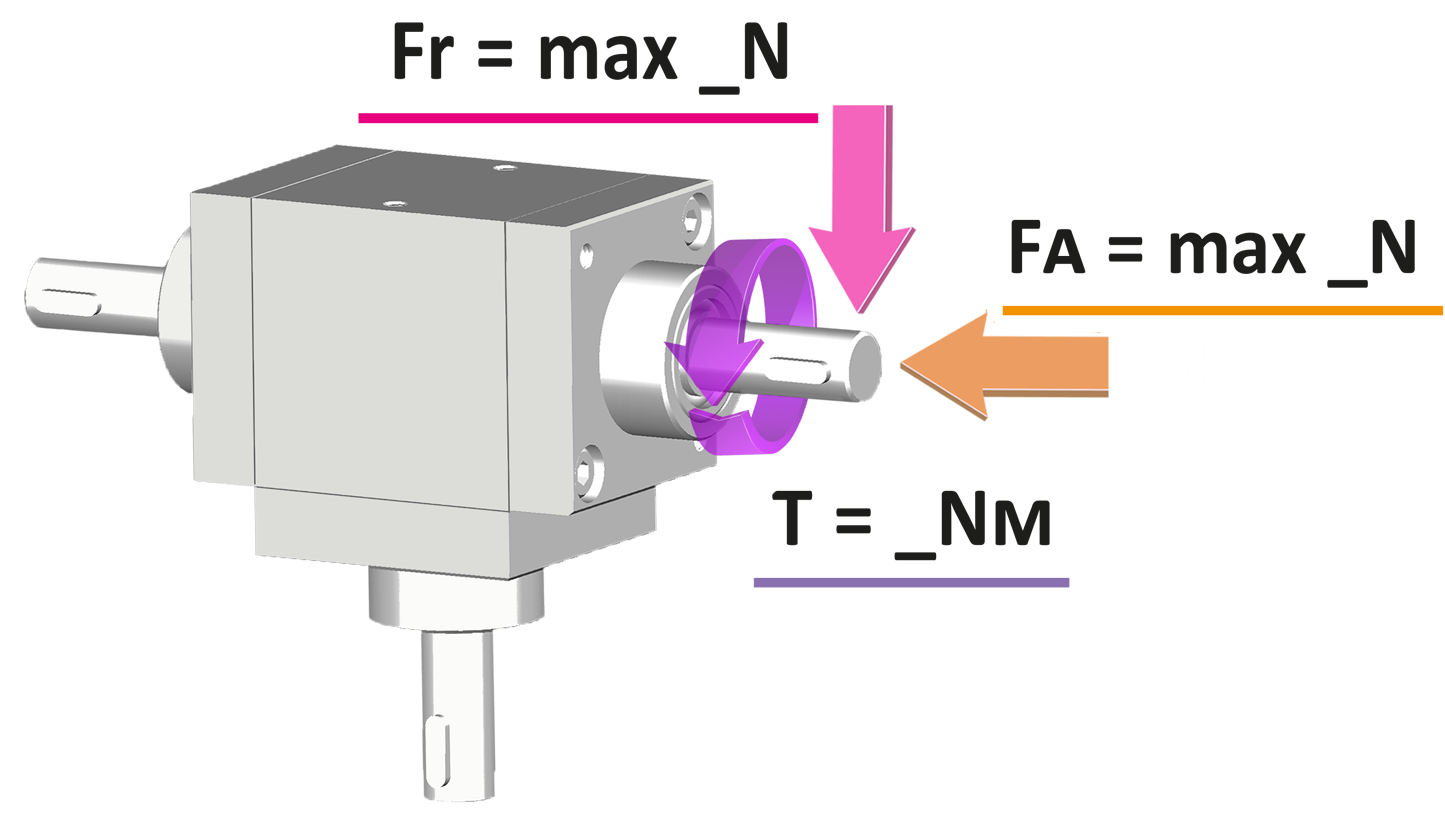
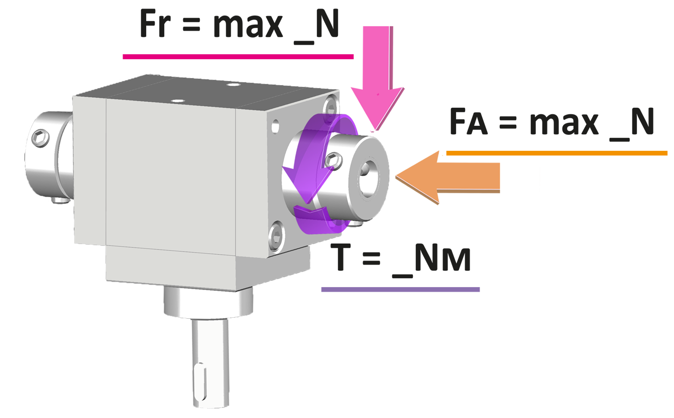
| REPRESENTATION OF LOADS | ||
|
«B» |
«D» |
|
 |
 |
|
|
Fr = radial load 750 N |
||
|
Note: a radial load (ex. belt tension) can only be applied to the long shaft of the «B» and «D» versions; otherwise, a support must be provided. |
||

COUPLING BUSHES 2 piece bushing to couple gearboxes and shafts.
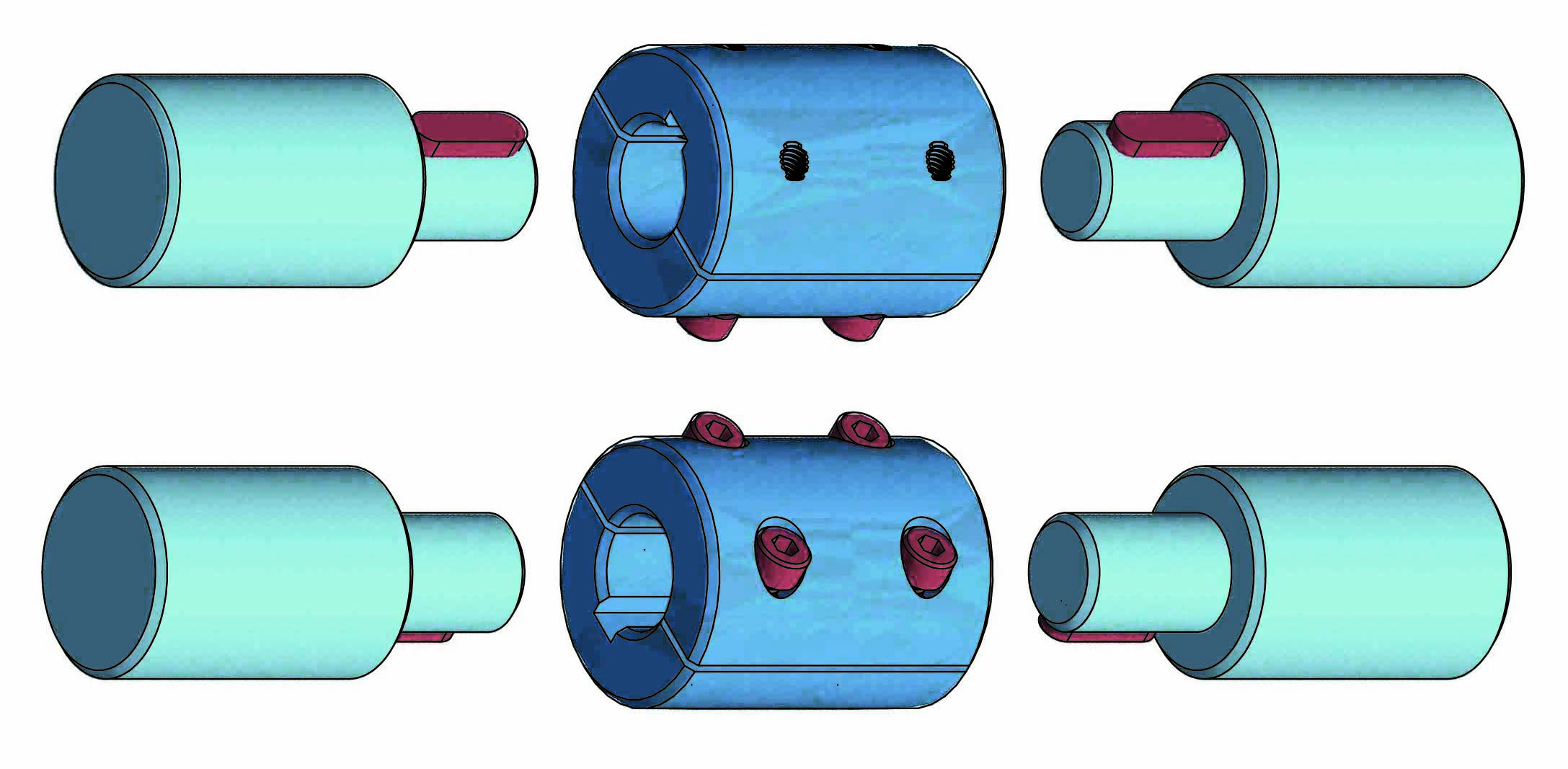
Available bores Ø: 6 - 8 -10 -14.
➜ for more complete information, see BT
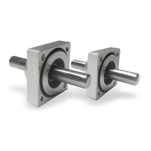
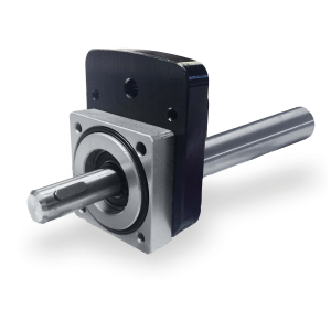
Flanged supports with extension shaft for coupling with position indicators.
➜ for more complete information, see Flanged supports
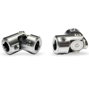
The «GC» and «GCC» cardan joints used for the transmission of torque and movement of non-aligned elements.
Main features: universal application, high reliability, maintenance free, extremely precise and ease-of-use.
• Case entirely machined from solid, in stainless steel AISI303.
• Suitable for intermittent (UI) and continuous movements (UC).
• Maximum working angle 45 °.
➜ for more complete information, see GC and GCC
Richiedi l'accesso
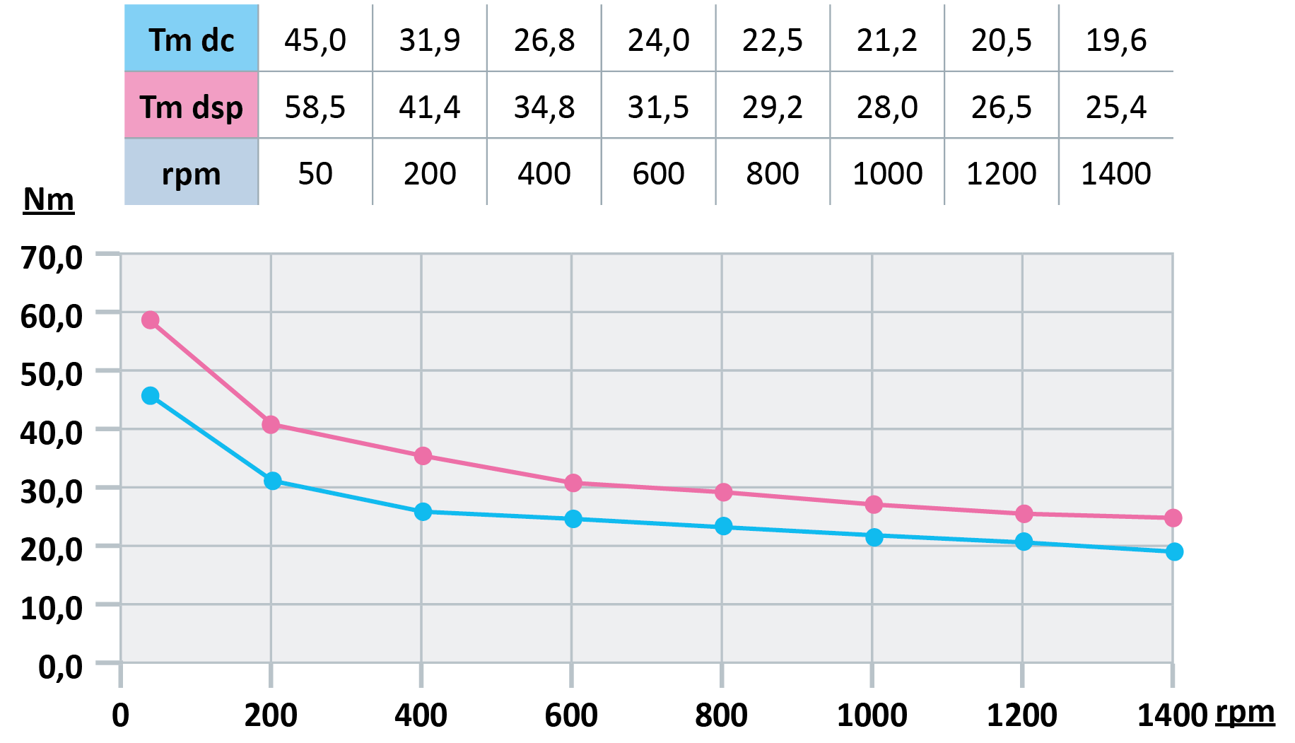
| OUTPUT TORQUE WITH RATIO 1/1 |
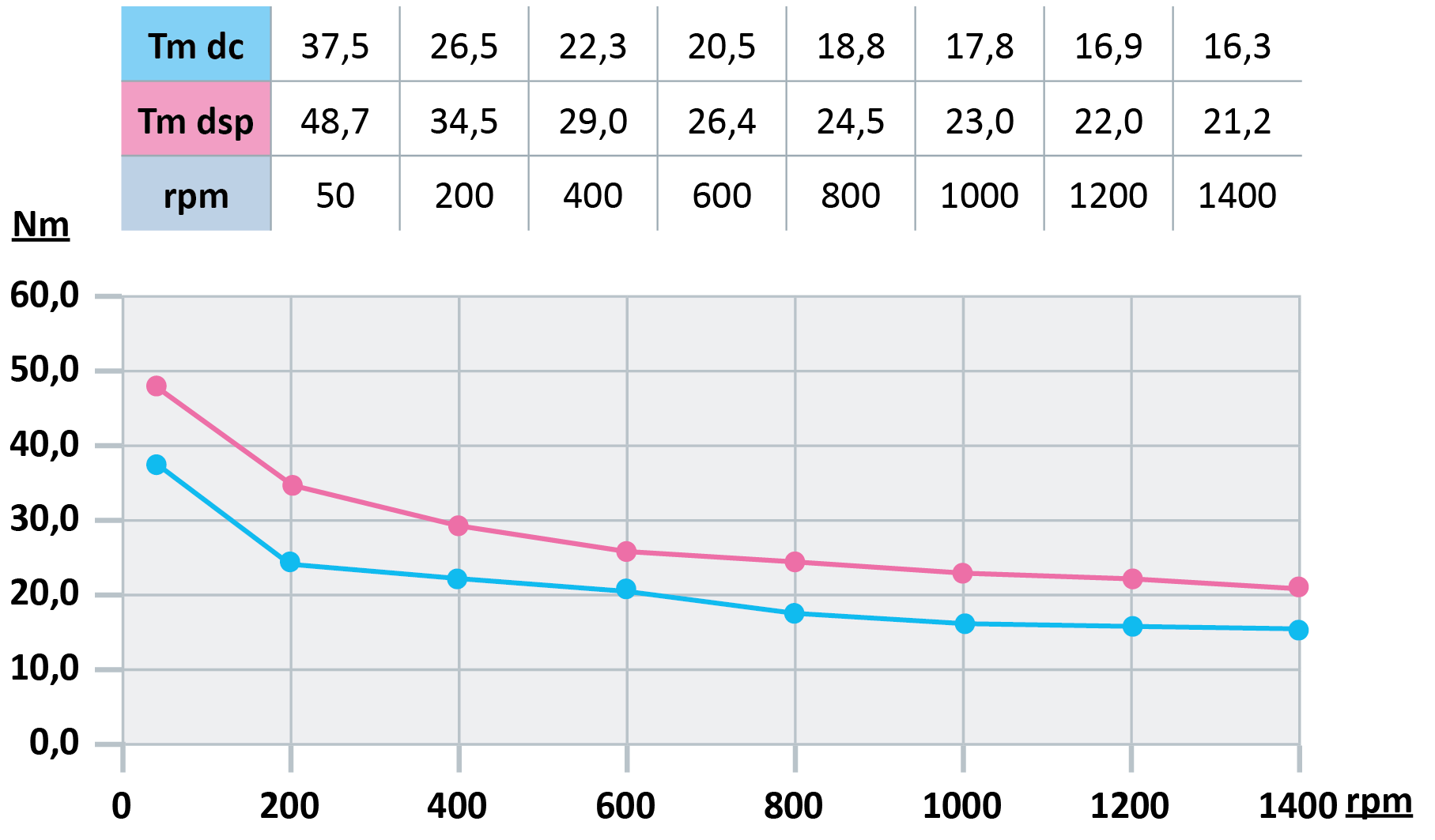
| OUTPUT TORQUE WITH RATIO 1/2 |
| OUTPUT TORQUE WITH RATIO 2/1 |
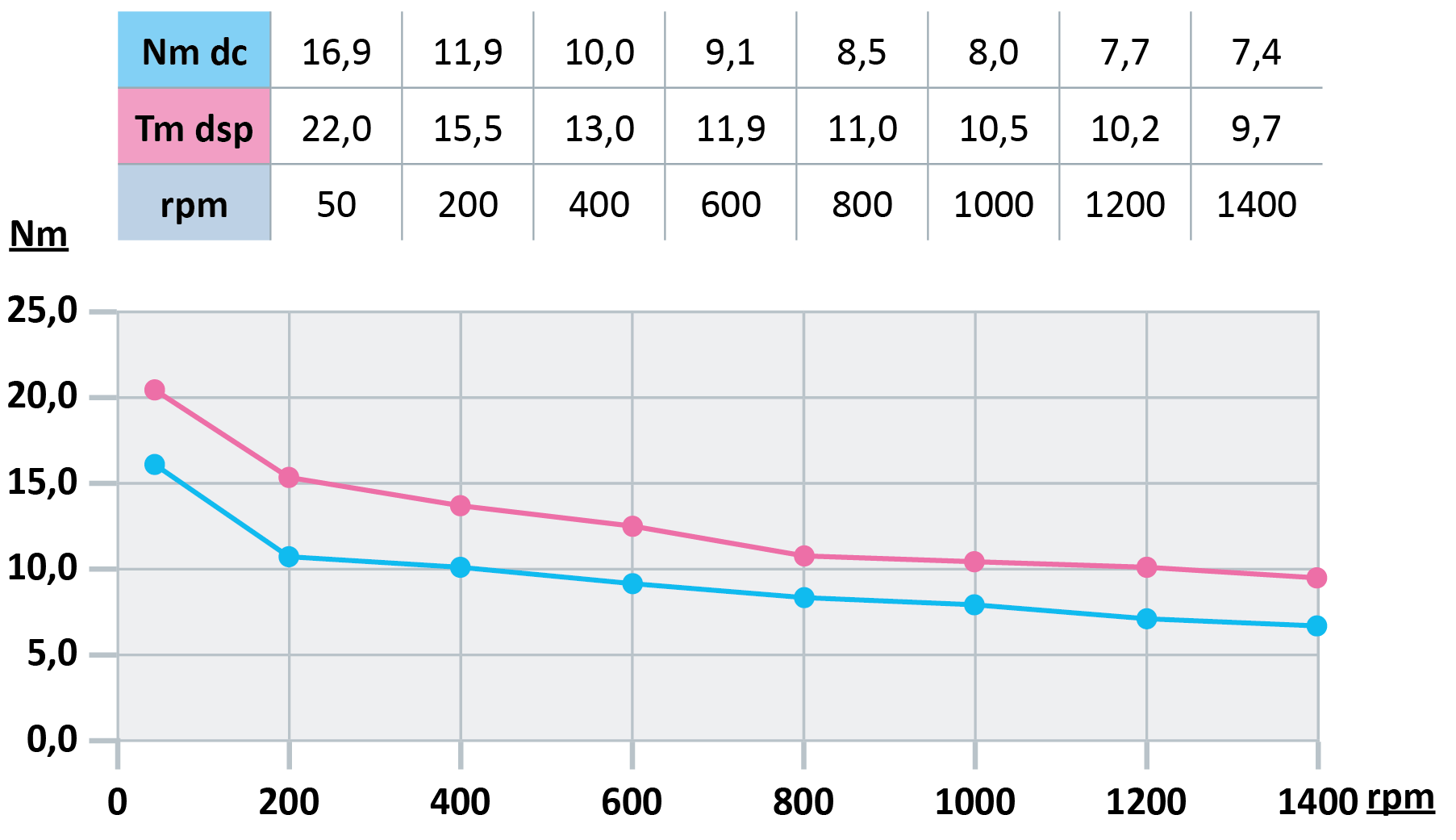
| Efficiency = 90% |
| - Tm = maximum torque in Nm |
| - dc = bevel gearing |
| - dsp = spiral gearing |


