
RINV-OP65
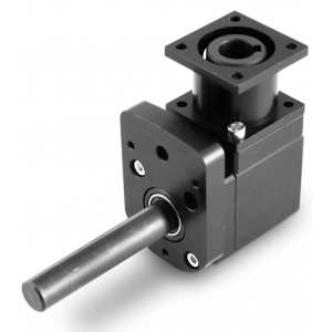
Angular flanged gearbox
The RINV-OP65 is a flanged angular gearbox that, combined with a mechanical position indicator type “OP7” or an electronic position indicator type “EP7”, allows to carry out a visualized adjustment, angular or linear, even if the shaft is in an uncomfortable position.
• Several orientations and connection possibilities.
• Available with ratios: 1:1 - 1:2 reduction - 2:1 moltiplication.
• Maximum output torque 12 Nm.
• Aluminium case, black anodized. Steel shafts. Steel bevel gears, case-hardened (Pronox).
• Movements on ball-bearings, water-proof.
• Radial load 25 kg - axial load 2,5 kg
• Weight gr. 550.
Photogallery


| RINV-OP65 |
 |
| A. 4 fixing bores Ø4-M4 |
| B. Spline 5x5 |
| C. N.3 M6-120° |
| D. Fixing flange OP7- EP7 |
| E. Hollow shaft Ø14x16 |
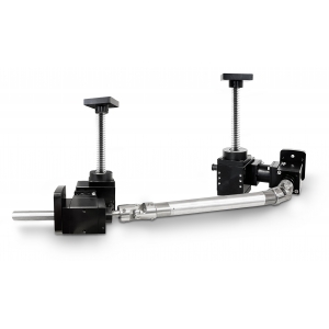
| EXAMPLES OF MOUNTING POSITIONS | |
 |
 |
 |
 |
The RINV-OP is supplied standard as per overall drawing.
To change the mounting position of the OP flange, screw-off the two fixing screws, turn the flange in desired position, and fix the two screws.
To fix the machine side, insert shaft Ø14 into the hollow shaft of the RINV-OP, and lock with fixing screws M6 or spline.


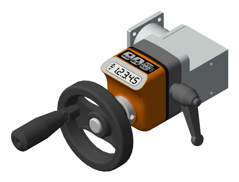
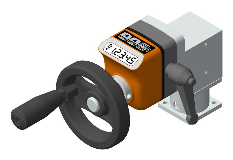
Control handwheel with folding handle, thermoplastic material, steel bush.
➜ for more complete information, see V.R

Crank handle with folding handle in thermoplastic material, steel bush.
➜ for more complete information, see V.M

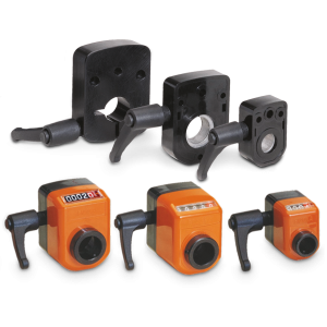
With the shaft block flange on the OP2, OP3, OP6, OP7, OP5, OP9 indicator as a compact unity, we obtain a safe blocking of the drive shaft.
➜ for more complete information, see FL-B


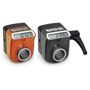
• 5 digits counter (standard red digit indicates decimals; on request 2 red digits for hundredths or 5 black digits for mm).
• Readings until 99999. ‘Lens to improve the reading’: digit height 7 mm.
• Standard shaft bore ø20 (OP7) or ø25 bore (OP7F25). Other holes smaller than 20 with reducing bush.
➜ for more complete information, see OP7
• Measures linear or angular movements, applicable to many types of industrial
• Simple assembly through the hollow shaft
• Powered by long battery life, easy replacement from the front
➜ for more complete information, see EP7
Photogallery


Richiedi l'accesso
| REPRESENTATION OF REDUCTION & MULTIPLYING RATIO | ||||
| Example | ||||
|
ratio 1:2 ---------------------------------- |
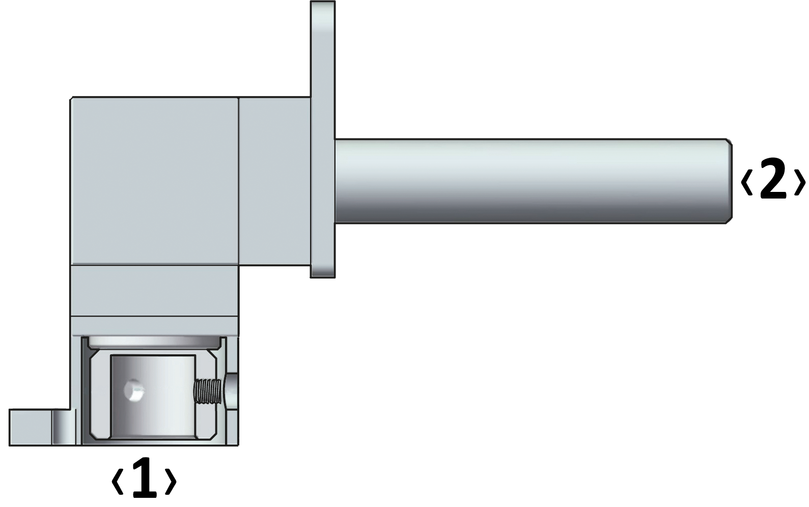 |
|||
|
‹1› = machine side |
||||
|
The ratio is determined by the shaft ‹1›. |
||||
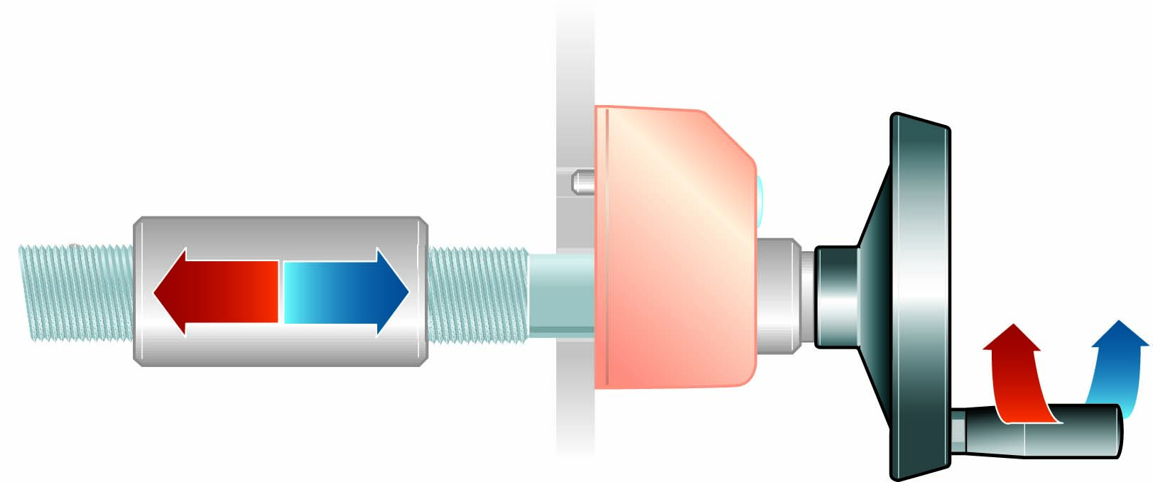
| RADIAL AND AXIAL LOAD | ||
| Fig. 8 | ||
 |
Fr = max 250 N radial load, is the load acting in perpendicular direction to the shaft/axise | |
|
Fa = max 25 N axial load, is the load acting of the shaft/axis |
||
| T = 12 Nm output torque | ||
|
The loads acting on the shafts can be of two types, referred to the axis of the shaft (Fig. 8): : |
| OUTPUT TORQUE WITH RATIO 1/1 |

| Efficiency = 90% |
| OUTPUT TORQUE WITH RATIO 1/2 |

| Efficiency = 90% |
| OUTPUT TORQUE WITH RATIO 2/1 |

| Efficiency = 90% |


