
Gear reducers & Screw jacks - General information
Versatile Solutions for Automation and Robotics: Screw Jakcs and Gear Reducers ideal for Lifting, Positioning, and Production Lines Across All Sectors
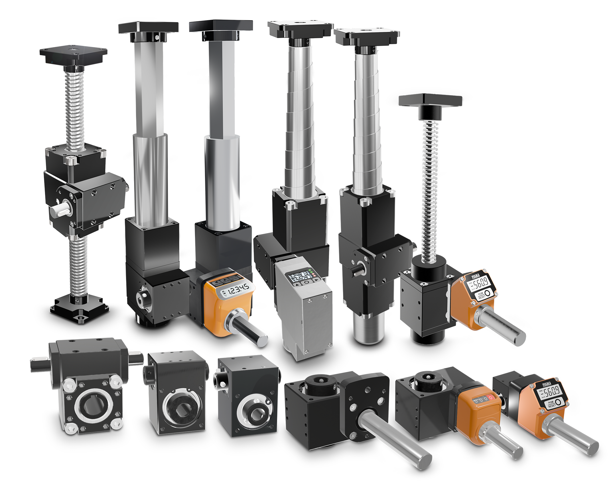
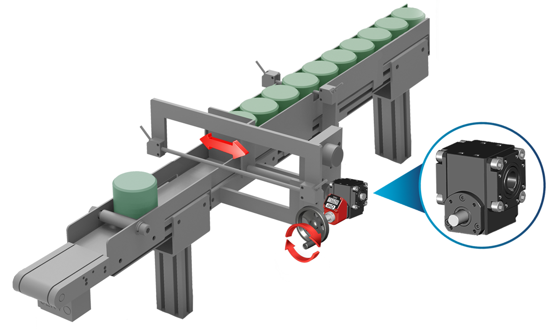
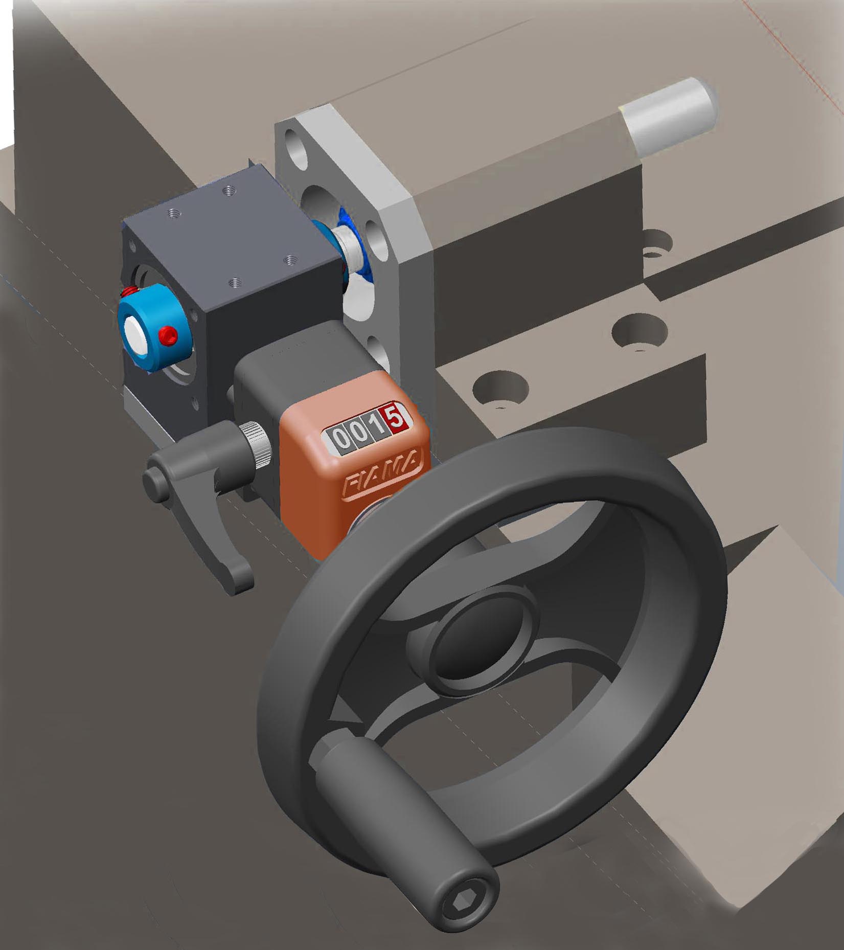
Gear Reducers – RD Series ➜ Transmission • Reduction • Precision
Designed to reduce speed and increase torque, ensuring high flexibility and adaptability for products of varying sizes, and characteristics.
– Key Features
• 4 sizes: RD26 – RD40 – RD50 – RD60
• Robust construction: black anodized aluminum housing; hardened steel shafts resistant to wear and corrosion
• Wide range: various reduction ratios and male/female shaft configurations
– Available Versions:
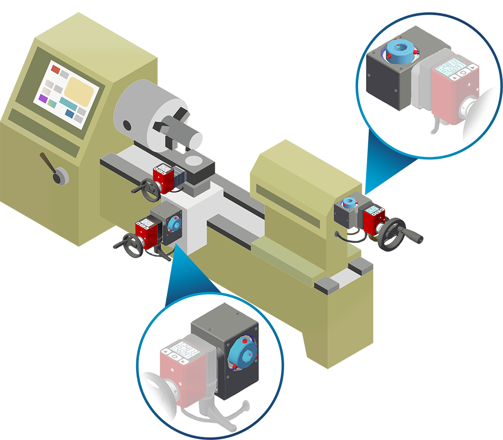
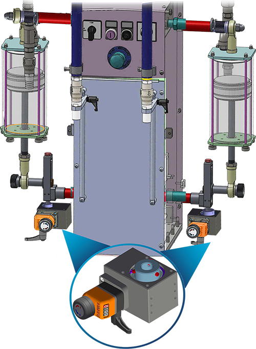
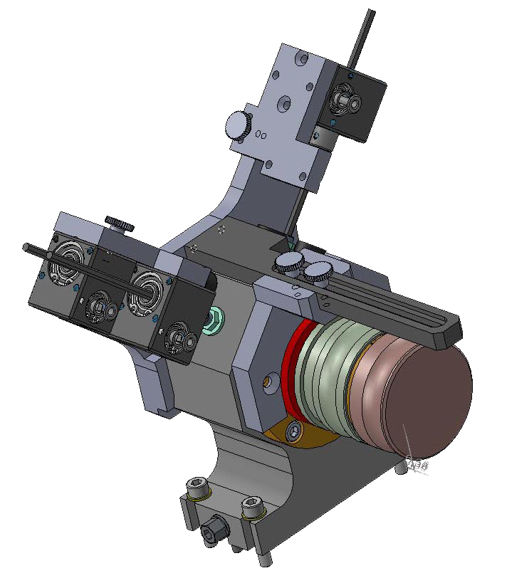
• Flanges + shaft extensions for OP2 – OP3 – OP7 – EP7 digital and electronic indicators
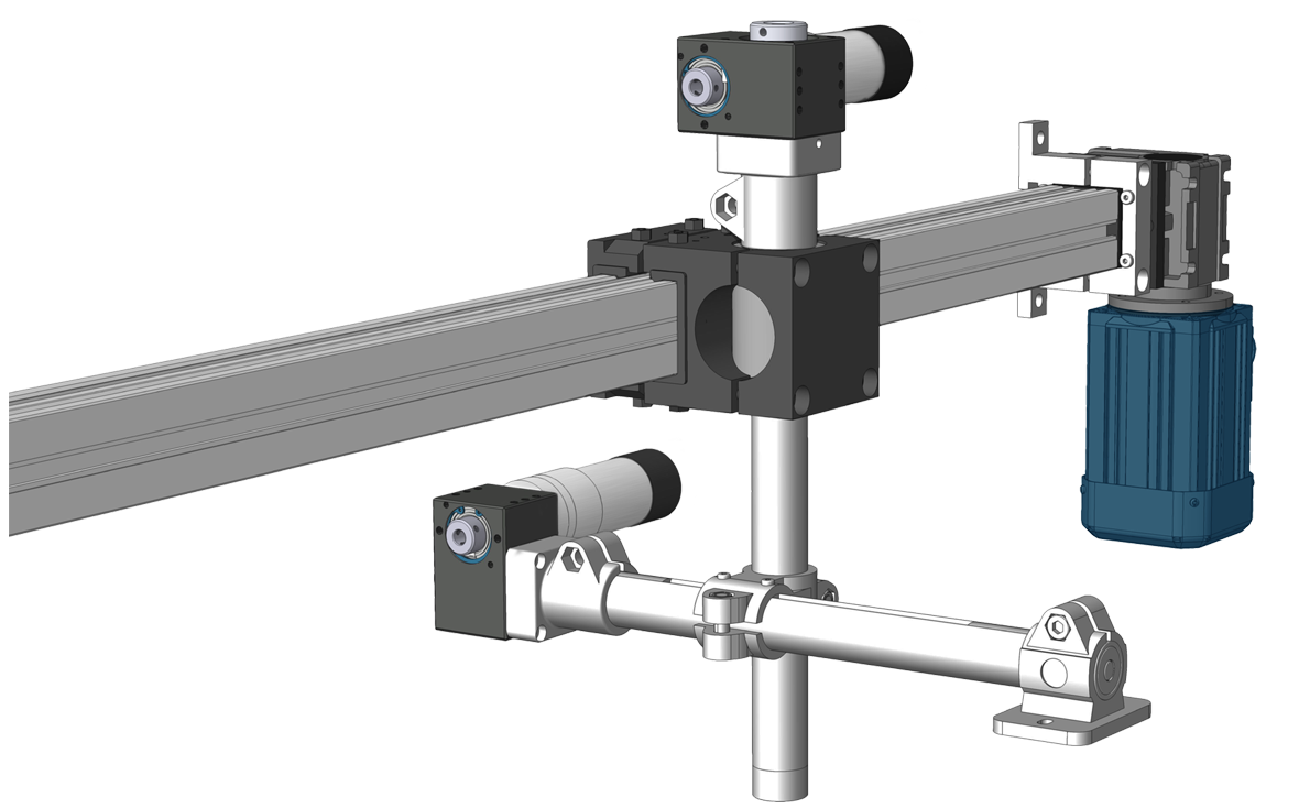
• Models with magnetic sensors, small motors, or geared motors
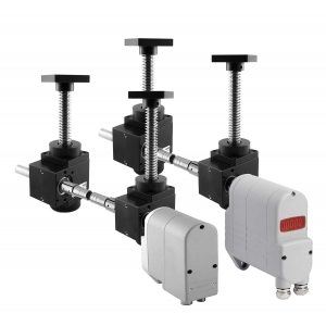
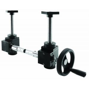
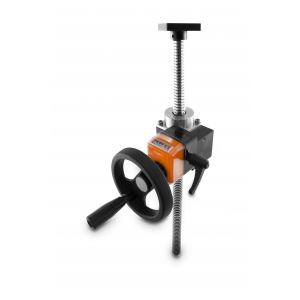
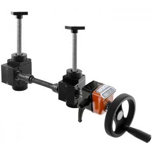
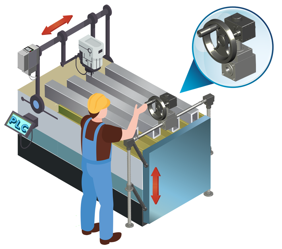
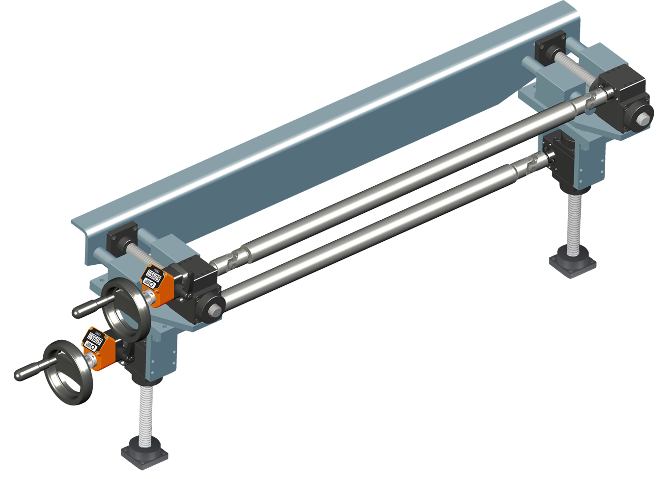
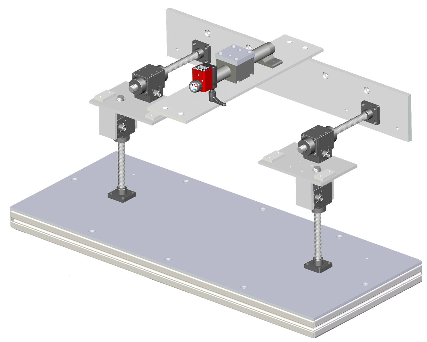
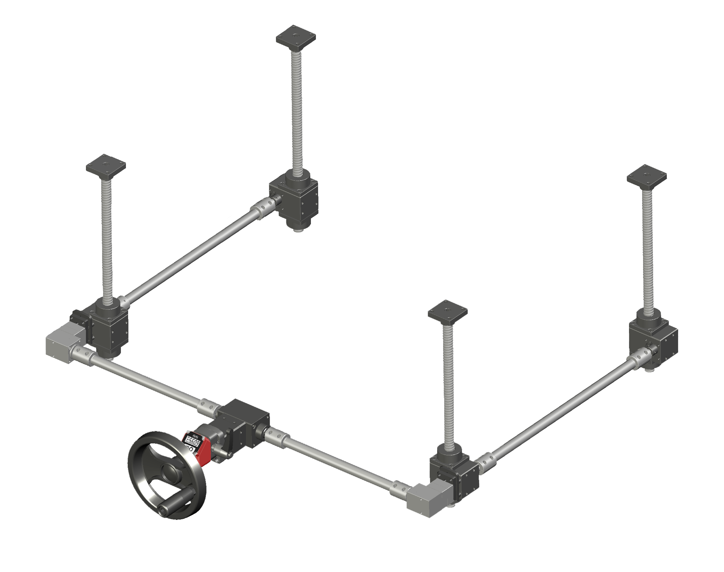
Screw Jacks – MAR Series ➜ Lifting • Positioning • Synchronization
Used to lift, pull, move, align, and position, providing versatile functionality adaptable to any requirement.
– Key Features
• 3 available sizes: MAR40 – MAR50 – MAR60
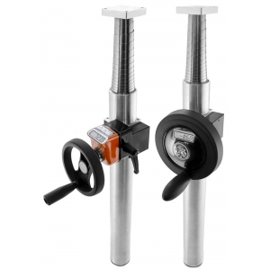
• Available versions: self-supporting and guided, or with upper and lower protection (aluminum or stainless steel)
• Wide range: various reduction ratios and configurations
• Construction: anodized aluminum housing; shafts and gears in hardened stee; trapezoidal screw in AISI 304 stainless steel
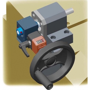
• Operation: manual or motorized
• Accessories and configurations: flanges for couplings, transmissions, angular gearboxes, motors, and indicators
– Available Versions:
• Self-supporting and guided, or with upper and lower protection (aluminum or stainless steel)
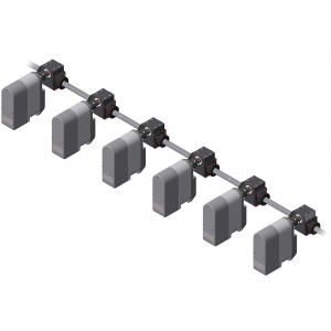
• Mounting flange and shaft extension for OP2 – OP3 – OP7 – EP7 digital and electronic indicators• Modular systems and turnkey solutions: can be used individually or in groups connected via shafts, couplings, and/or angular gearboxes
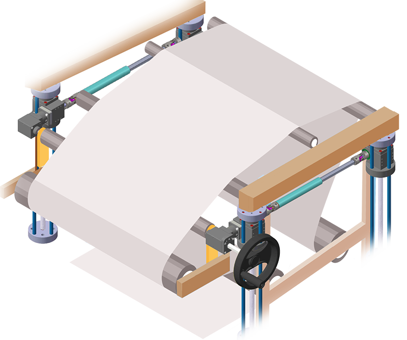
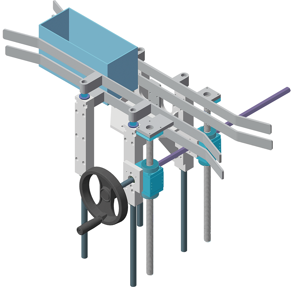
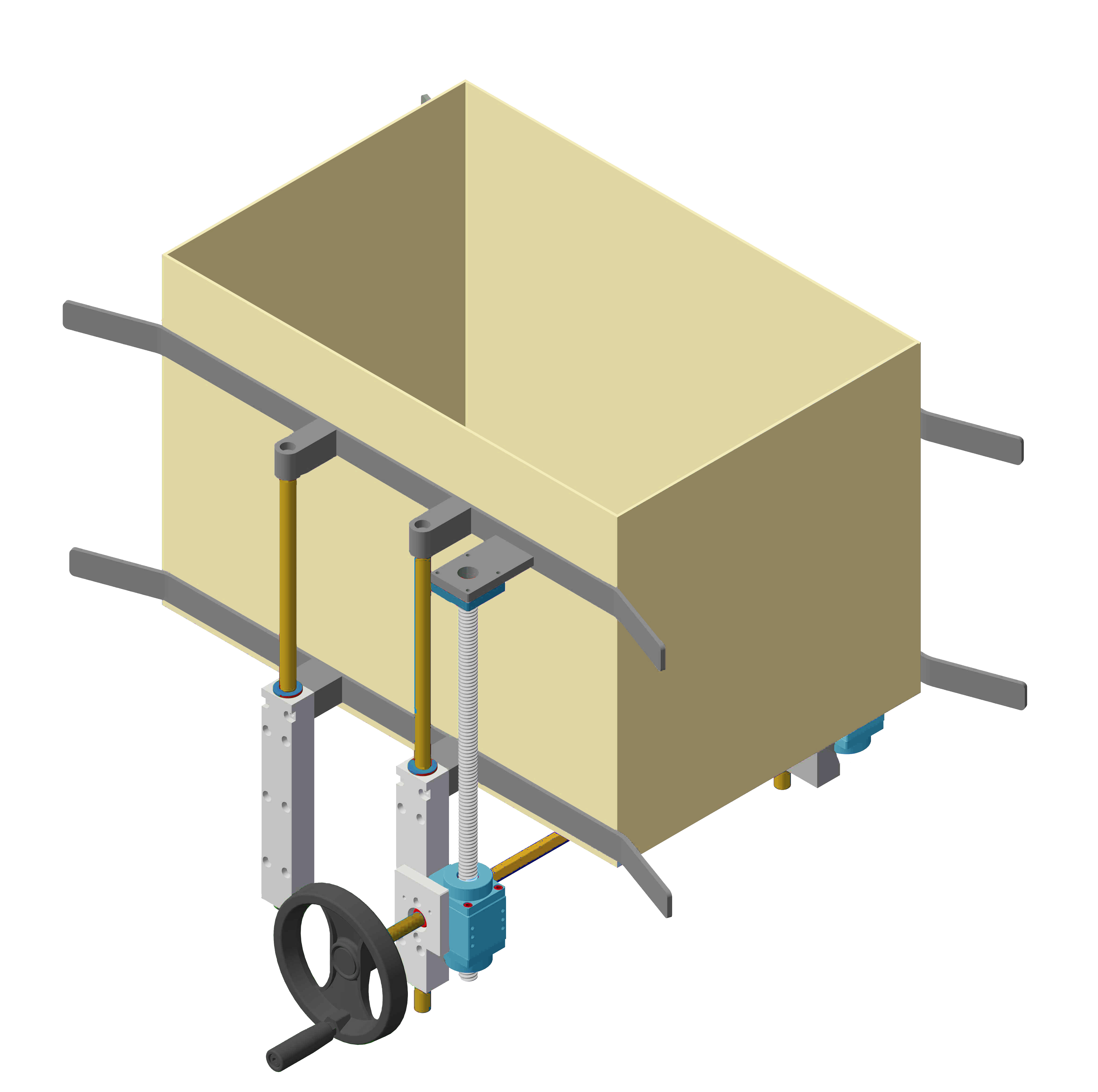
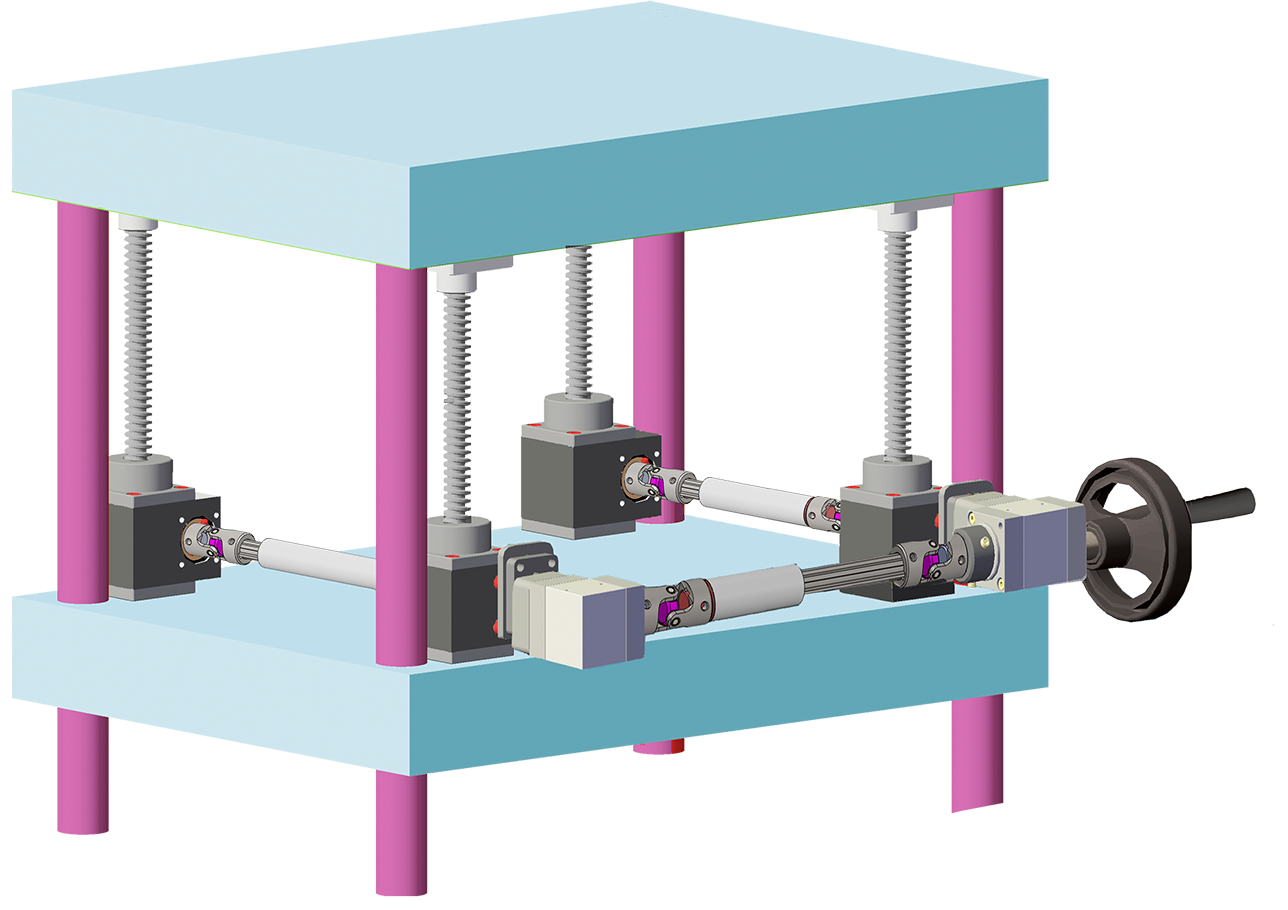
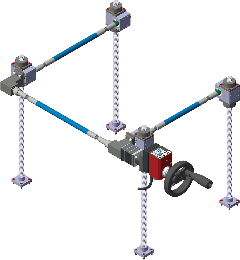
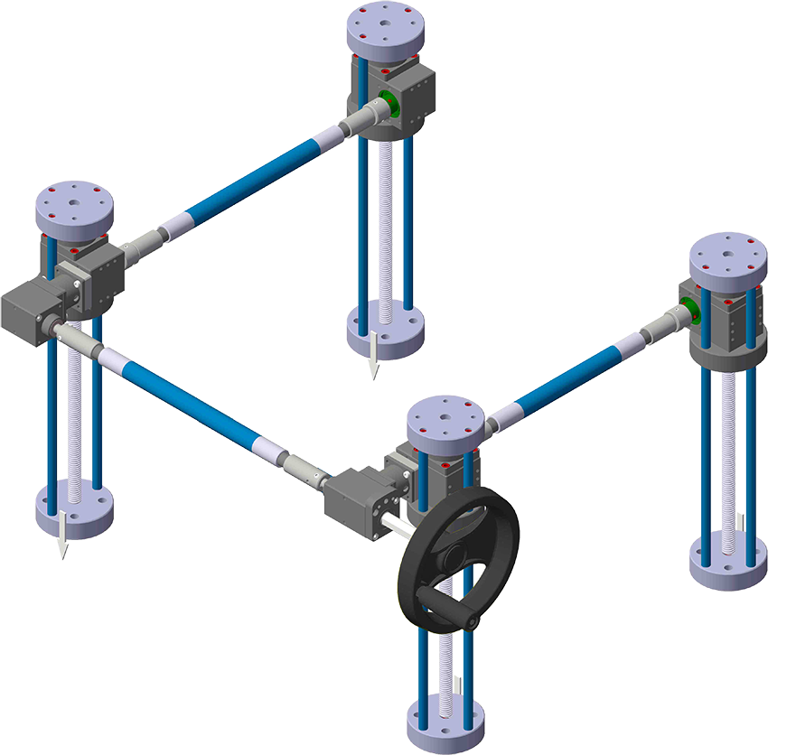
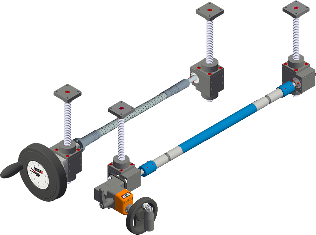
Photogallery
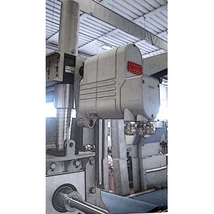
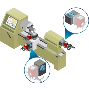
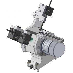
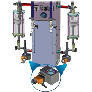
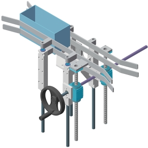

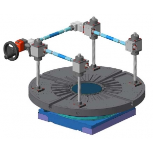
| APPLICATION EXAMPLES |
 .
. 


.png)


|
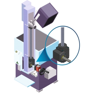
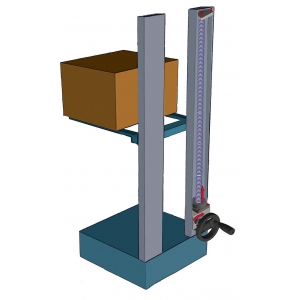
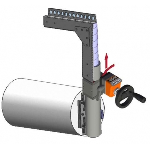
SCREW JACK SIZING VERIFICATION |
|
• Load (Kg) = the handled weight which is applied to the threaded bar of the screw jack |
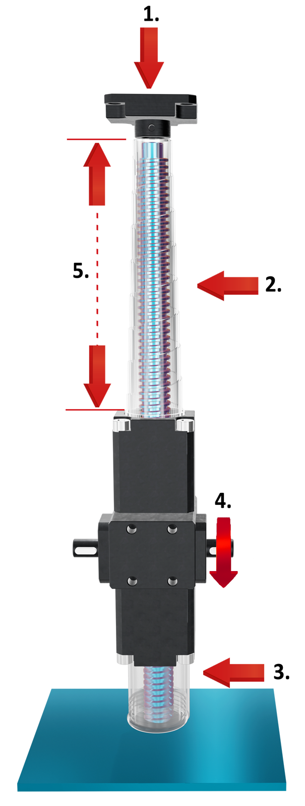 |
| 1. Load (Kg) |
| 2. Upper spiral protection (optional) |
| 3. Lower rigid protection (optional) |
| 4. Rpm (max. 1500) |
| 5. Stroke (mm) |
|
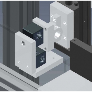
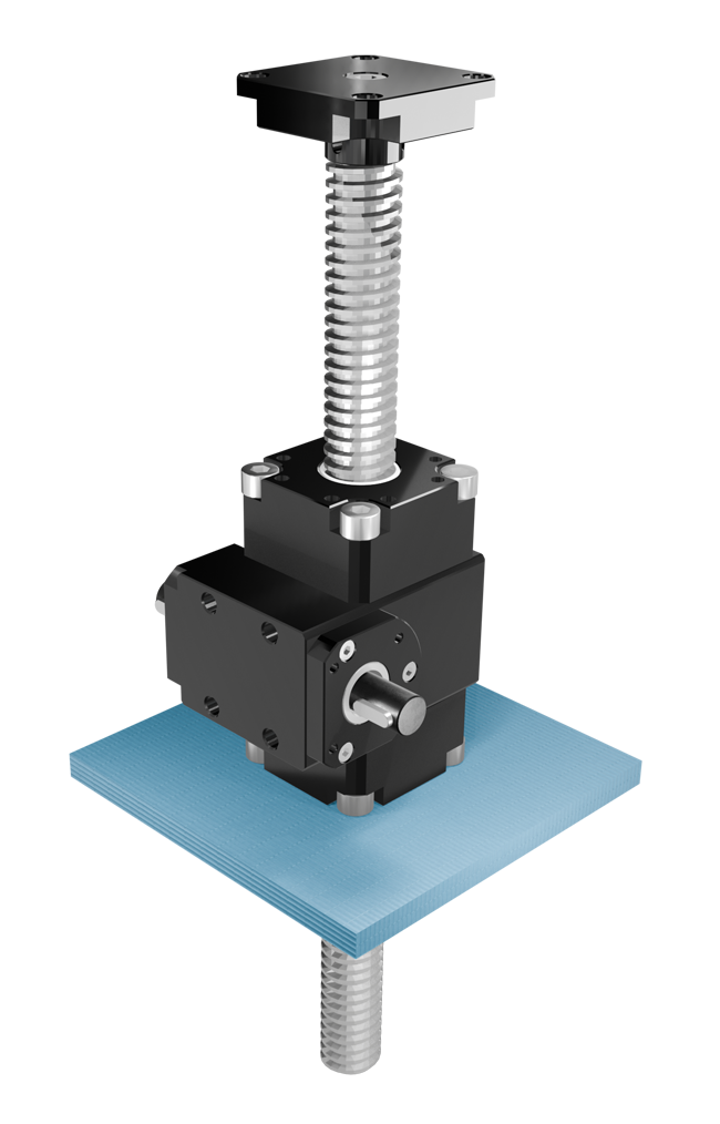
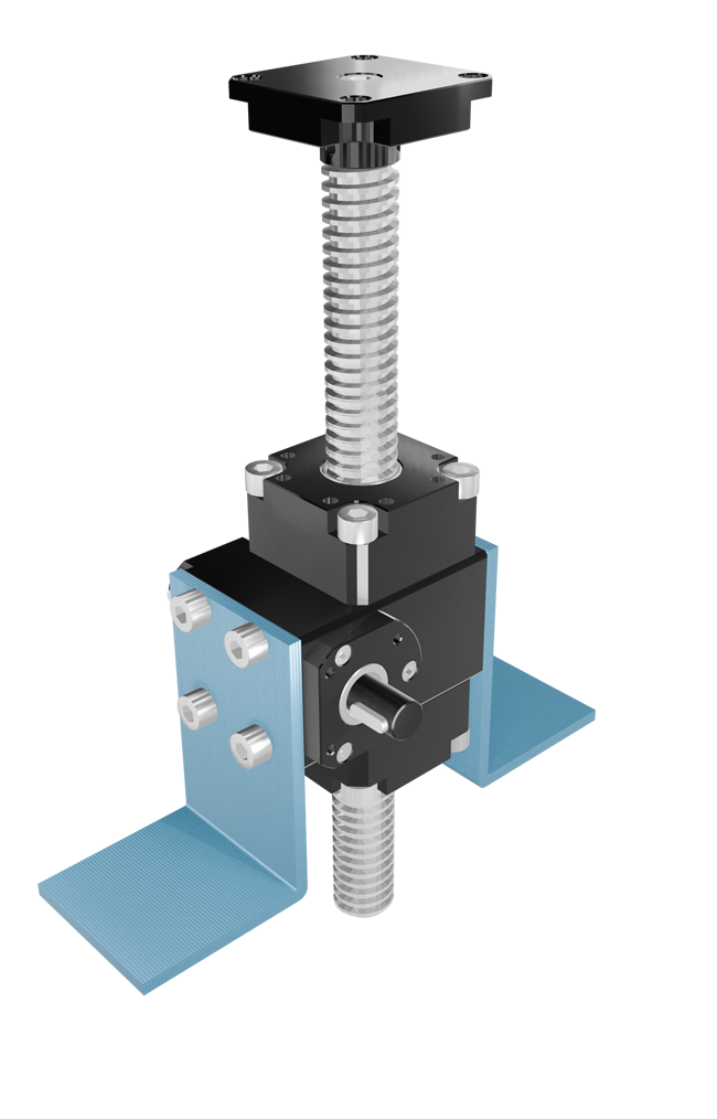
SUPPORT AND MOUNTING |
|
|
Trapezoidal screw jacks require adequate structural support (not included in the supply) to ensure proper load movement and system stability. The unit must be firmly secured to the machine structure using a flat, rigid, and perfectly aligned base. |
|
|
Based on the application configuration: |
|
 |
 |
|
Bottom support: |
Side support: |
|
Benefits of correct installation: minimizes internal wear and ensures accurate, long-lasting operation. |
|
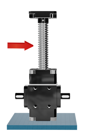
| INSTALLATION | |
 |
 |
|
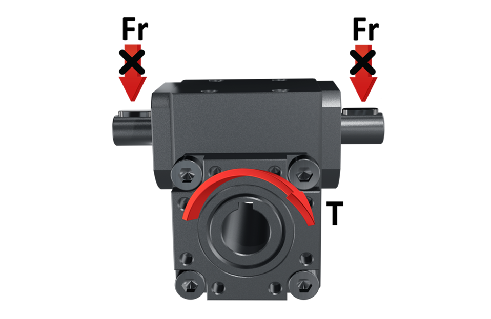
Installation must not create radial/lateral loads, which are the main cause of failure, on the threaded bar. |
The plane to which the screw jack is fixed and the threaded bar must be orthogonal and the load and the bar must be coaxial avoiding eccentricity. |
 |
|
|
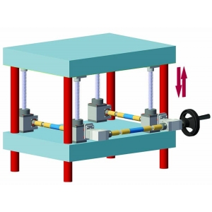
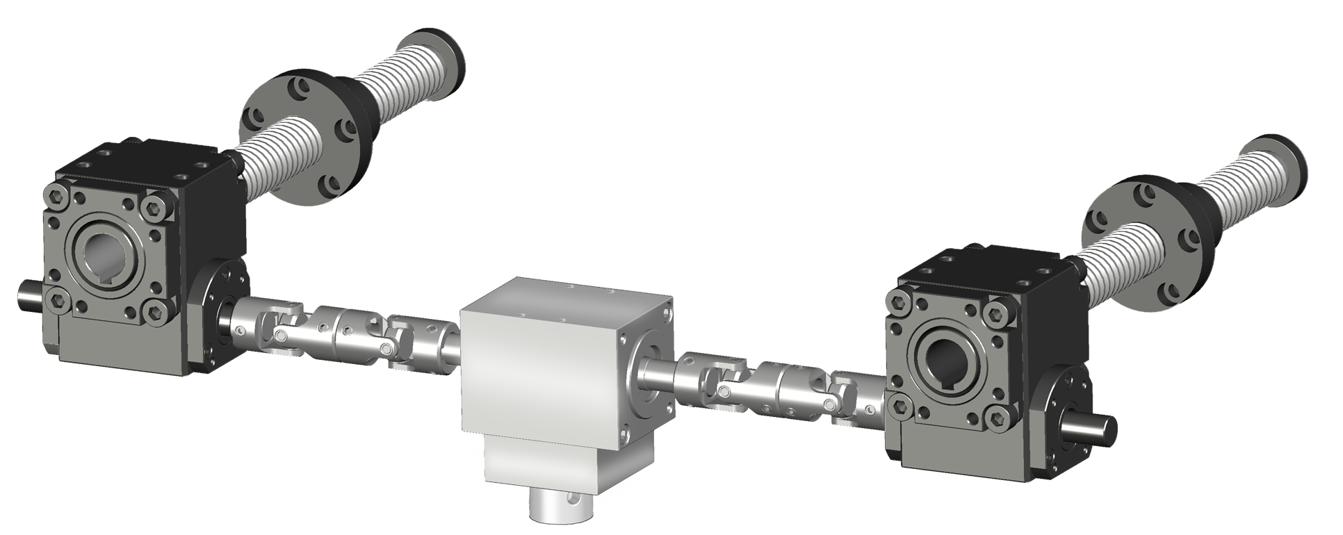
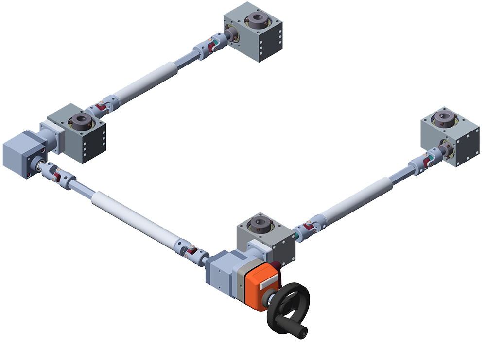
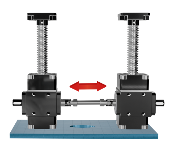
When applying multiple screw jacks (connected also by transmissions) the terminals must be perfectly aligned so that the load is uniformly distributed; in this case it is recommendable to use couplings to compensate misalignments. |
|
Richiedi l'accesso
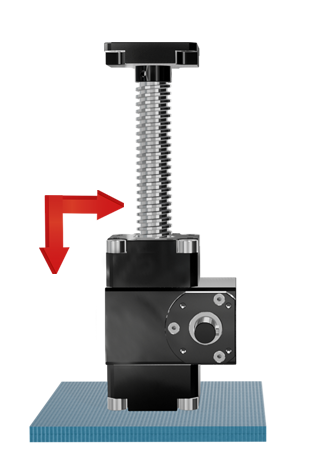
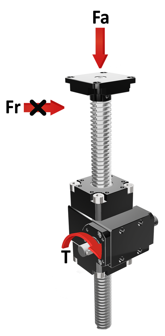
| REPRESENTATION OF LOADS |
|
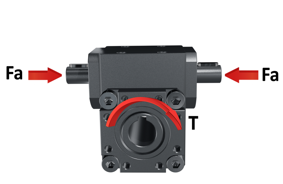
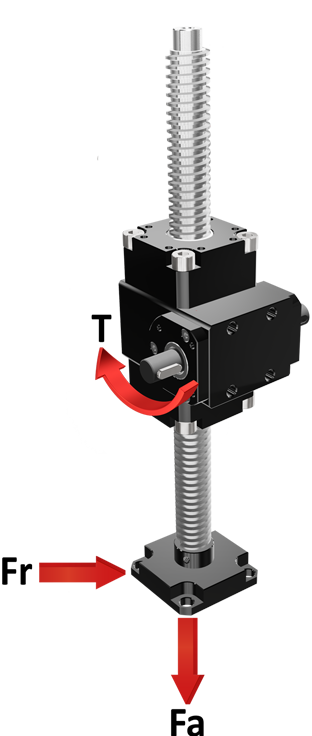
The loads acting on shafts, with reference to the shaft axis, can be radial (Fr) or axial (Fa). For screw jacks, the loads can be in tension or compression (to be specified when ordering). Fr = radial force/load, acting perpendicular to the shaft/axis Note: the maximum allowable values of Fr, Fa, and T depend on the model and operating conditions. |
|
Axial Force |
Pull |
Push |
 |
 |
|
| Radial Force | ||
 |
|
Calculation applied to all models |
| THEORETIC EXPECTED LIFE✽ = 10.000H X Fu
|
✽ The lifetime of 10.000h considers the following conditions:
• Applied torque = advised torque (see tables)
• Maximum of 8 working hours per day
• Working temperature 20 °
• No shocks
• Ta Output torque actually applied
• Max torque applied (see tables/models)
|
GLOSSARY |
|
FR = radial force |
|
FA = axial force |
| R = efficiency |
| T = torque |
| Tm = maximum torque |
| Tr = recommended torque |
| Ta = applied torque |
| To = output torque |
| Ti = input torque |
| Pn = power |
| N = Newton |
| Nm = Newton meter |
| fu = use coefficient |
| i = transmission ratio |
| rpm = revolutions per minute (1/min) |
| n1 = input shaft |
| n2 = output shaft |
| M = protruding / male shaft |
| F = blind hollow shaft / female |
| F = through hollow shaft / female |
| ⦿ For correct sizing is necessary to know: transmitted power (Pn), output torque (T) andinput rotation speed (rpm). |
|
⦿ To identify the most suitable gearbox for your requirements, refer to the values in the table. If the real loads and efficiency are very close to the table values, contact the technical department. |
|
⦿ All tables show linear measurements expressed in <mm>, unless otherwise specified. All the reduction ratios are expressed as a <fraction> unless otherwise specified. All forces are expressed in N, loads in kg, torques in Nm, and efficiencies in %, unless otherwise specified. |


