
OP9
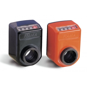
Position indicator with hollow shaft
• 5 digits counter (standard red digit indicates decimals; on request 2 red digits for hundredths or 5 black digits). Model OP9T: 4 digits with graduated digit. Readings until 99999. Digit height: 7 mm.
• Shock-proof self-extinguishing technopolymer case. Protection IP64. Max. temperature 80°C.
• Reading with 18° tilted or frontal view.
• OP9 standard shaft hole ø20 or ø30, version OP9F35 hole ø35, different holes with reducing bush.
• Lock-pin: centre distance 40mm (standard).
On request:
• On request special ratios and measures in Inch.
• Lock-pin: centre distance 30mm.
• Model “IN” with metallic parts in stainless steel.
• Colours: orange RAL 2004, black RAL 9005.
• Available accessories: shaft block flange, handle, handwheel (see drop-down menu on the right).
Photogallery


1. Lock pin
2. Dust seal
3. ø 49x15 embedding
4. Fixing screw
| MOUNTING POSITION | |||
 |
 |
 |
|
| VIEW «A» for horizontal shaft tilted, top view |
VIEW «B» for vertical shaft, side view |
VIEW «C» for horizontal shaft, low front view |
VIEW «D» for horizontal shaft, top front view |
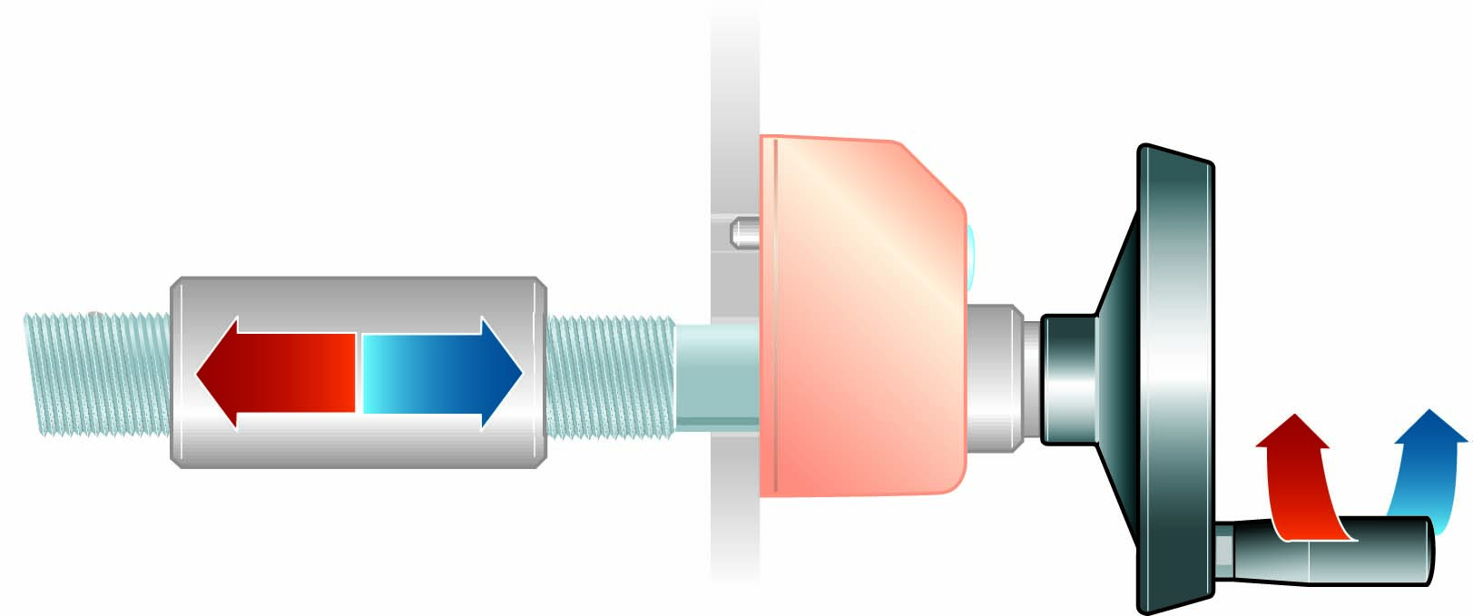
| Introduce the indicator through the hollow shaft and set the lock pin into the arranged hole. Set the instrument on the inner (zero) value and block the fixing screw. | |||

| DISPLAY | |
 |
for decimal indication (standard) |
 |
for hundredths indication with dashes |
 |
for hundredths indication (2RR) |
 |
for millimeters indication (4RN) |
|
DIRECTION OF ROTATION |
| DX increasing values with clockwise rotation, decreasing values with anti-clockwise rotation |
 |
| SX increasing values with anti-clockwise rotation, decreasing values withclockwise rotation |


Reducing technopolymer bushes for OP.
➜ for more complete information, see BF

Reducing bushes for shaft block flange OP (technopolymer).
➜ for more complete information, see BF-BL

Control handwheel with folding handle, thermoplastic material, steel bush.
➜ for more complete information, see V.R

Crank handle with folding handle in thermoplastic material, steel bush.
➜ for more complete information, see V.M

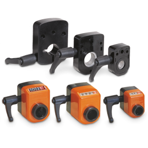
With the shaft block flange on the OP2, OP3, OP6, OP7, OP5, OP9 indicator as a compact unity, we obtain a safe blocking of the drive shaft.
➜ for more complete information, see FL-B
Richiedi l'accesso


INDICATION AFTER 1 REVOLUTION
1R = 1 red digit (decimals)
2RR = 2 red digits (hundreths)
5RN = 3 cifre nere (millimeters)
(") = indication in inches
Vmax = referred to decimal indication (0,1)
Vmax" = referred to indication in inches
| 1R | 2RR | 5RN | (") | Vmax | Vmax" |
|---|---|---|---|---|---|
| 0,1 | 0,01 | mm | inches | rpm | rpm |
|
00010 |
00010 |
00010 |
00039(37) |
300 |
60 |
|
00015 |
00015 |
00015 |
300 |
||
|
00020 |
00020 |
00020 |
00078(74) |
200 |
200 |
|
00025 |
00025 |
00025 |
200 |
||
|
00030 |
00030 |
00030 |
00011(81) |
200 |
200 |
|
00040 |
00040 |
00040 |
00015(74) |
150 |
150 |
|
00050 |
00050 |
00050 |
00019(68) |
150 |
150 |
|
00060 |
00060 |
00060 |
100 |
||
|
00075 |
00075 |
00075 |
80 |
||
|
00080 |
00080 |
00080 |
80 |
||
|
00100 |
00100 |
00100 |
00039(37) |
60 |
200 |
|
00120 |
00120 |
00120 |
60 |