OP5
Position indicator with hollow shaft

• 5 digits counter (standard red digit indicates decimals; on request 2 red digits for hundredths or 5 black digits). Readings until 99999. Digit height mm 5,5
• It is possible to reverse the counting direction ratios from «pitch 1 to pitch 15».
• Shock-proof, self-extinguishing technopolymer case. Protection IP54. Max. temperature: 70°C .
• Reading with 45° inclination view.
• Standard shaft hole: ø20 H7; different holes smaller than 20 with reducing bush.
On request:
• Model “AZZ” with button for positioning and zero-setting, with 4 digits counter, in ratios from «pitch 1 to pitch 6».
• Special ratios and measures in Inch.
• Version “IN” with inox metallic parts.
• Colours: orange RAL 2004, black RAL 9005
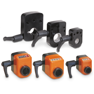
• Available accessories (see p. 30): shaft block flange, handle, handwheel (see drop-down menu on the right).

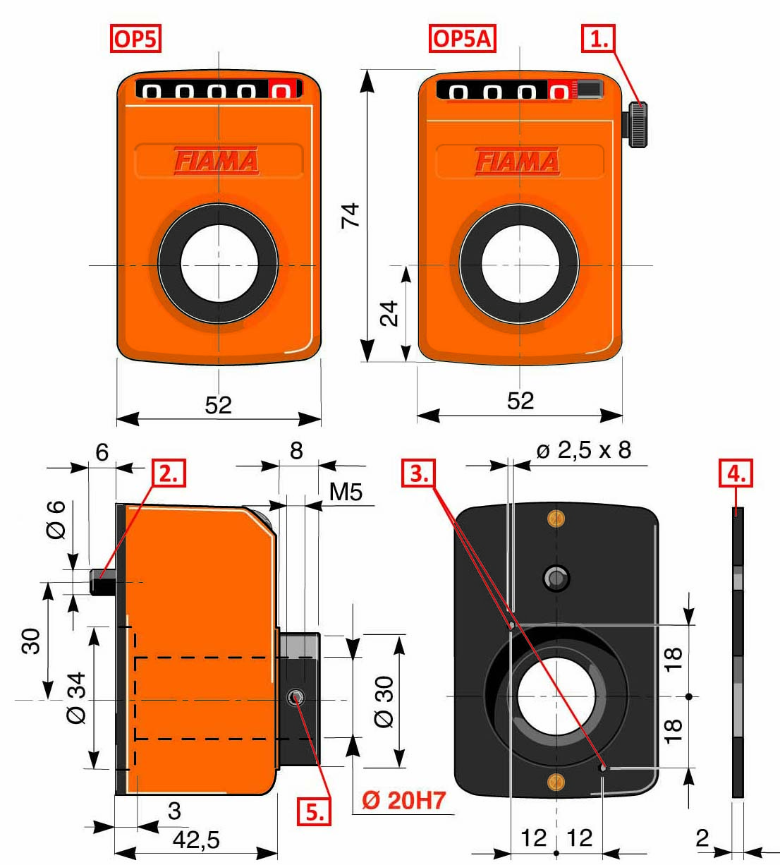
1. Positioning push button
2. Lock pin
3. 2 Ø2,5x8 fixing holes
4. Dust seal
5. Fixing screw
| MOUNTING POSITION | |
 |
 |
| VIEW «A» for horizontal shaft tilted, top view |
VIEW «B» for vertical shaft, side view |
| Introduce the indicator through the hollow shaft and set the lock pin into the ø5 or ø6 (b type) arranged hole. Set the instrument on the inner (zero) value and block the fixing screw. | |
| DISPLAY | |
 |
for decimal indication (standard) |
 |
for hundrethstel indication (2RR) |
 |
for indication in millimetri (5RN) |
 |
for decimal indication with 0-button (3RN-1RR) |
| REVERSAL COUNTING DIRECTION |
 |
|
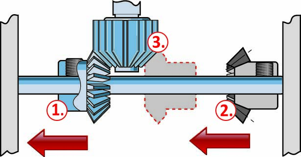
Remove the cover. Move gear ① to the left, then move gear ② to left and engage it with gear ③ (in ratios from «pitch 1 to pitch 15»). |
| DIRECTION OF ROTATION | COUNTER with 0-button |
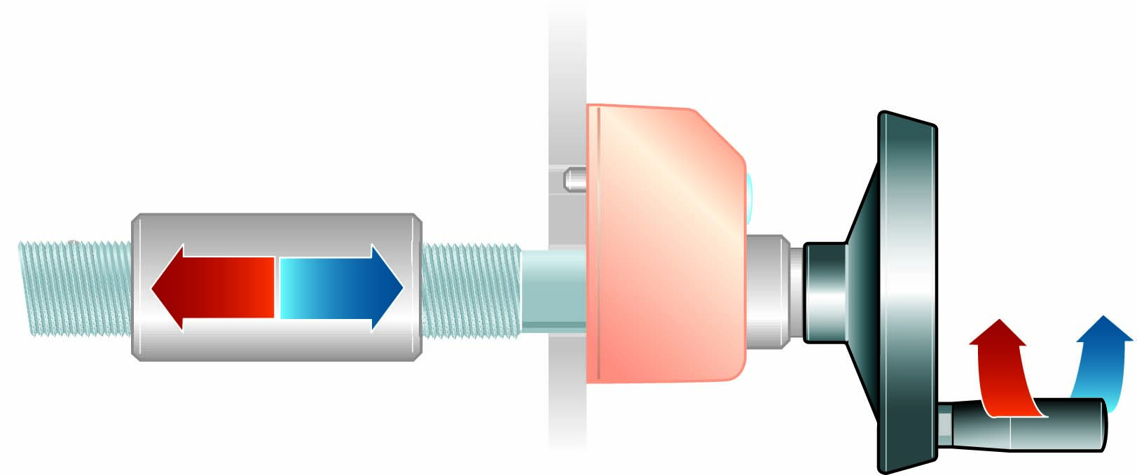
| DX increasing values with clockwise rotation, decreasing values with anti-clockwise rotation | |
 |
 |
| SX increasing values with anti-clockwise rotation, decreasing values withclockwise rotation |

Reducing technopolymer bushes for OP.
➜ for more complete information, see BF

Reducing bushes for shaft block flange OP (technopolymer).
➜ for more complete information, see BF-BL

Control handwheel with folding handle, thermoplastic material, steel bush.
➜ for more complete information, see V.R


Crank handle with folding handle in thermoplastic material, steel bush.
➜ for more complete information, see V.M


With the shaft block flange on the OP2, OP3, OP6, OP7, OP5, OP9 indicator as a compact unity, we obtain a safe blocking of the drive shaft.
➜ for more complete information, see FL-B
Richiedi l'accesso
INDICATION AFTER 1 REVOLUTION
1R = 1 red digit (decimals)
2RR = 2 red digits (hundreths)
5RN = 3 cifre nere (millimeters)
(") = indication in inches
Vmax = referred to decimal indication (0,1)
Vmax" = referred to indication in inches
| 1R | 2RR | 5RN | (") | Vmax | Vmax" |
|---|---|---|---|---|---|
| 0,1 | 0,01 | mm | inches | rpm | rpm |
|
00001 |
00001 |
00001 |
600 |
||
|
00002 |
00002 |
00002 |
600 |
||
|
00004 |
00004 |
00004 |
600 |
||
|
00005 |
00005 |
00005 |
600 |
||
|
00008 |
00008 |
00008 |
00031(49) |
600 |
200 |
|
00010 |
00010 |
00010 |
00039(37) |
500 |
200 |
|
00015 |
00015 |
00015 |
500 |
||
|
00020 |
00020 |
00020 |
00078(74) |
400 |
200 |
|
00025 |
00025 |
00025 |
00098(42) |
400 |
200 |
|
00030 |
00030 |
00030 |
00011(81) |
200 |
100 |
|
00040 |
00040 |
00040 |
00015(74) |
200 |
100 |
|
00050 |
00050 |
00050 |
0019(68) |
200 |
400 |
|
00060 |
00060 |
00060 |
200 |
||
|
00075 |
00075 |
00075 |
100 |
||
|
00080 |
00080 |
00080 |
100 |
||
|
00100 |
00100 |
00100 |
100 |
||
|
00120 |
00120 |
00120 |
60 |
||
|
00150 |
00150 |
00150 |
60 |


